Suzuki GSX-R 1000 Service Manual: Exhaust emission control system description
The exhaust emission control system is composed of the pair system, exhaust control system, ho2 sensor, threeway catalyst system and isc system. The fresh air is drawn into the exhaust ports through the pair control solenoid valve and pair reed valves. The pair control solenoid valve is operated by the ecm, which is controlled according to the signals from tps, ects, iaps and ckps. The exhaust gas flow is performed by the exhaust control valve actuator which is controlled by the ecm by changing the exhaust control valve angle. Isc valve adjusts the bypass air volume of the throttle body to control engine idling speed with various sensor signals by varying engine running conditions.
|
 Crankcase emission control system
description
Crankcase emission control system
description
The engine is equipped with a pcv system to prevent discharging crankcase
emissions into the atmosphere. Blow-by
gas in the engine is constantly drawn into the crankcase, which is returned to
the ...
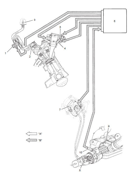
 Pair system diagram
Pair control solenoid valve
Pair reed valve
Fresh air
Exhaust gas
...
Other materials:
Drive chain cleaning and lubricating
Clean and lubricate drive chain
every 1 000 km (600 miles)
Clean and lubricate the drive chain in the following
procedures:
clean the drive chain with kerosine. If the drive chain
tends to rust quickly, the intervals must be
shortened.
Caution
do not use trichloroethyle ...
Rear brake hose routing diagram
Hose clamp
: face the clamp end backward.
Stopper
: after the brake hose union has contacted
to the stopper, tighten the union bolt.
Brake pad pin
Plug
Caliper sliding pin b
Caliper sliding pin a
White marking
Yellow marking
Pass the
...
Starter motor removal and installation
Removal
Turn the ignition switch off and disconnect the
battery (–) lead wire (1).
Lift and support the fuel tank. Refer to “fuel tank
removal and installation” in section 1g (page 1g-
9).
Disconnect the starter motor lead wire (2).
Remove the starter motor (3).
...