Suzuki GSX-R 1000 Service Manual: Gear position (gp) switch removal and installation
Removal
- Turn the ignition switch off.
- Lift and support the fuel tank. Refer to “fuel tank removal and installation” in section 1g (page 1g- 9).
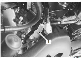
- Disconnect the gear position switch lead wire coupler (1).
- Remove the engine sprocket cover. Refer to “engine sprocket removal and installation” in section 3a .
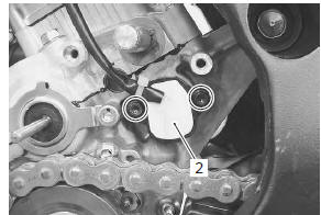
- Remove the gp switch (2).
Installation
Install the gear position switch in the reverse order of removal. Pay attention to the following points:
- apply grease to the o-ring.
| Caution replace the o-ring with a new one. |
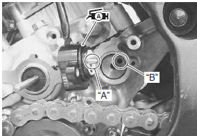
| Note align the gear position switch pin “a” with the gearshift cam hole “b”. |
 : Grease 99000–25010 (suzuki
super
grease “a” or equivalent)
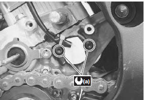
- Tighten the gear position switch mounting bolts to the specified torque.
Tightening torque gear position switch mounting bolt (a): 6.5 N·m ( 0.65 Kgf-m, 4.5 Lbf-ft)
- Route the gear position switch lead wire. Refer to “wiring harness routing diagram” in section 9a .
 Transmission related parts inspection
Refer to “transmission removal” , “transmission installation” and
“countershaft gear / driveshaft gear disassembly and assembly” .
Gearshift fork to groove clearance
Note
the clear ...
 Gearshift lever construction
Gearshift lever bracket
Gearshift lever shaft
Washer
Snap ring
Gearshift lever
Footrest top surface
65 – 75 Mm (2.6 – 3.0 In)
28 N·m (2.8 Kgf-m,
...
Other materials:
Body frame construction
Frame
Seat rail
Seat rail bolt
Collar
Engine mounting thrust adjuster
Engine mounting thrust adjuster lock-nut
Engine mounting pinch bolt
50 N·m (5.0 Kgf-m,
36.0 Lbf-ft)
23 N·m
(2.3 Kgf-m, 16.5 Lbf-ft)
45 N·m
(4.5 Kgf-m, 32. ...
Specifications
Service data
Electrical
Tightening torque specifications
Note
the specified tightening torque is described in the following.
“Wiring harness routing diagram”
Reference: for the tightening torque of fastener not specified in this
section, refer to “tightening torque l ...
Engine sprocket removal and installation
Removal
Remove the gearshift link arm (1) from the gearshift
shaft.
Note
mark the gearshift shaft head at which the
gearshift link arm slit set for correct
reinstallation.
Remove the speed sensor (2).
Remove the engine sprocket cover (3).
Support the ...