Suzuki GSX-R 1000 Owners Manual: Ignition switch

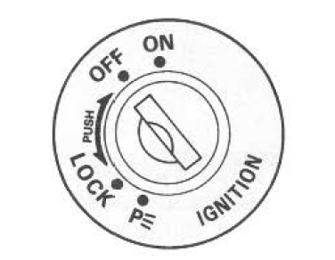
The ignitionr switch has 4 positions:
"Off" position
All electrical circuits are cut off.
The engine will not start. The key can be removed.
"On" position
The ignition circuit is completed and the engine can run. The headlight and taillight will automatically turn on. The key cannot be removed in this position.
Note
: start the engine promptly after turning the key to the "on" position, or the battery will lose power due to consumption by the headlight and taillight.
"Lock" position
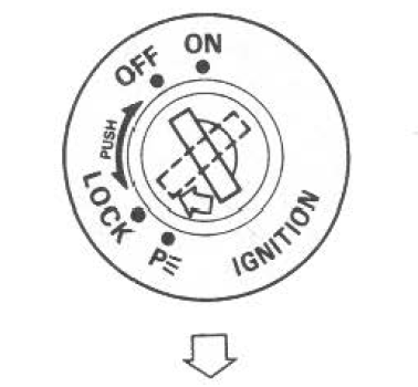
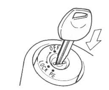
All electrical circuits are off. The key can be removed and the steering will be locked. Turn the steering all the way to the left and push down the key and turn it to the "lock" position.
"P" (parking) position
Taillight will come on to increase visibility for temporary road side parking at night. The key can be removed and the steering will be locked.
 Warning Warning
Moving the motorcycle while the steering is locked can be hazardous. You could lose your balance and fall, or you could drop the motorcycle. Stop the motorcycle and place it on the side stand before locking the steering. Never attempt to move the motorcycle when the steering is locked. |
Note
: the key hole can be covered by turning the lid for antitheft purpose.

Turn the ignition switch to "lock" position and change the lid hole position when leaving your motorcycle.


Align the lid hole position with the key hole position when inserting the key.
 Key
Key
Two keys come with this motorcycle.
Keep the spare key in a safe
place. An identifying number is
stamped on the plate. Use this
number when making a replacement
key.
Please write down yo ...
 Instrument panel
The fuel indicator light 8,12,13
Lcd's and tachometer needle
work as follows to confirm their
function when the ignition switch
is turned to the "on" position.
The fuel indicator ...
Other materials:
Gearshift linkage inspection
Refer to “gearshift shaft / gearshift cam plate removal and installation” .
Gearshift shaft
Check the gearshift shaft for bend or wear.
Check the return spring for damage or fatigue.
If any defects are found, replace the defective part(-s).
Gearshift shaft oil seal
Inspect the gearshif ...
Valve seat repair
The valve seats (1) for both the intake and exhaust
valves are machined to three different angles. The seat
contact surface is cut at 45°.
Intake valve
Exhaust valve
Caution
the valve seat contact area must be
inspected after e ...
Drive chain cleaning and
oiling
Clean and oil the chain as follows:
Wash the chain with kerosene.
Kerosene will lubricate and
clean the chain.
Warning
Kerosene can be hazardous .
Kerosene is flammable. Children
or pets may be harmed
from contact with kerosene.
Keep flames and smoking
mater ...
