Suzuki GSX-R 1000 Service Manual: Immobilizer description (for e-02, 19, 24, 51)
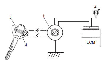
The immobilizer, an anti-theft system, is installed as a standard equipment.
The immobilizer verifies that the key id agrees with ecm id by means of radio communication through the immobilizer antenna. When the id agreement is verified, the system makes the engine ready to start.
|
|
Operation
When the ignition switch is turned on with the engine stop switch in on, the immobi-antenna and ecm are powered on.
The ecm transmits a signal to the transponder through the immobi-antenna in order to make comparison between the key id and ecm id.
With the signal received, the transponder transmits the key id signal to ecm so that ecm can make comparison with its own id, and if it matches, the engine is made ready to start.
|
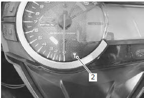
Also, when the ignition switch is turned on, the indicator light flashes as many as the number of ids registered in ecm. Thereafter, if the ids are in agreement, the indicator light turns on for two seconds to notify of completion in successful communication.
If the indicator light (led) flashes fast, it notifies of communication error or disagreement of id.
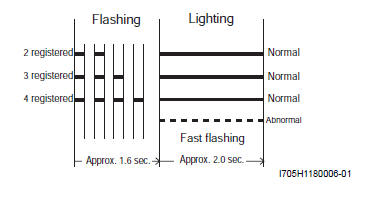
| Note if the indicator light flashes fast, turn the ignition switch off then on to make judgment again as there is possible misjudgment due to environmental radio interference. |
| Caution when the battery performance is lowered in winter (low temperature), the system may at times makes a re-judgment at the time of beginning the starter motor operation. In this case, the indicator light operation starts immediately after the starter operation. |
|

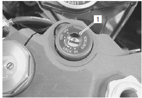
 Drive mode selector description
Engine power characteristics can be changed in 3
modes by operating the drive mode selector to meet
various riding conditions and rider’s preference.
Operation
Drive mode is preset at a-mode w ...
Other materials:
Crankcase breather (pcv) hose / reed
valve / cover removal and installation
Removal
Lift and support the fuel tank with the prop stay.
Refer to “fuel tank removal and installation” in section 1g .
Remove the air cleaner box. Refer to “air cleaner box removal and
installation” in section 1d .
Disconnect the crankcase breather (pcv) hose (1).
...
Rear shock absorber inspection
Refer to “rear shock absorber removal and installation” .
Shock absorber
Inspect the rear shock absorber for damage and oil
leakage, and absorber bushing for wear and damage. If
any defect is found, replace the rear shock absorber with
a new one.
Caution
do not attempt to disassemble ...
Front wheel assembly construction
Brake disc bolt
Brake caliper mounting bolt
Front axle bolt
Front axle pinch bolt
Clearance
18 N·m (1.8 Kgf-m,
13.0 Lbf-ft)
39 N·m
(3.9 Kgf-m, 28.0 Lbf-ft)
100 N·m
(10 kgf-m, 72.5 Lbf-ft)
23 N·m
(2.3 Kgf-m, 16.5 Lbf-ft)
...