Suzuki GSX-R 1000 Service Manual: Rear brake master cylinder assembly removal and installation
Refer to “rear brake hose routing diagram” (page 4a- 2).
Removal
- Remove the right side frame cover. Refer to “exterior parts removal and installation” in section 9d .
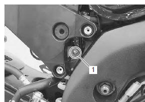
- Remove the rear brake fluid reservoir mounting bolt (1).
- Drain brake fluid. Refer to “brake fluid replacement” .
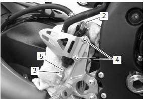
- Place a rag underneath the brake hose union bolt (2) on the master cylinder to catch any spilt brake fluid.
- Remove the brake hose union bolt (2).
- Loosen the lock-nut (3).
- Remove the master cylinder mounting bolts (4).
- Remove the master cylinder along with the reservoir by turning the push rod (5).
Installation
Install the rear brake master cylinder in the reverse order of removal. Pay attention to the following points:
| Caution the seal washers should be replaced with the new ones to prevent fluid leakage. |
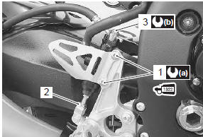
- Apply thread lock to the master cylinder mounting bolts (1) and tighten them to the specified torque.
 : Thread lock cement
99000–32110
(thread lock cement super “1322” or
equivalent)
- Tighten the lock-nut (2) temporarily.
- After setting the brake hose union to the stopper, tighten the union bolt (3) to the specified torque.
Tightening torque rear brake master cylinder mounting bolt (a): 10 n·m (1.0 Kgf-m, 7.0 Lbf-ft) brake hose union bolt (b): 23 n·m (2.3 Kgf-m, 16.5 Lbf-ft)
- Bleed air from the brake system after reassembling the master cylinder. Refer to “air bleeding from brake fluid circuit” .
- Adjust the brake pedal height. Refer to “brake pedal height inspection and adjustment” .
- Install the removed parts.
 Rear brake master cylinder components
Reservoir cap
Plate
Diaphragm
Reservoir tank
Reservoir hose
Brake hose
Brake hose union bolt
Brake hose connector
Master cylinder
Spring
Pis ...
 Rear brake master cylinder disassembly and assembly
Refer to “rear brake master cylinder assembly removal and installation” .
Disassembly
Disconnect the reservoir hose (1).
Remove the lock-nut (2).
Remove the brake hose connector ...
Other materials:
Headlight beam adjustment
Adjust the headlight beam, both horizontally and
vertically.
Note
to adjust the headlight beam, adjust the
beam horizontally first, then vertically.
It is not necessary to remove the
combination meter to turn the adjusters.
Horiz ...
Engine coolant temperature indicator light inspection
Inspect the engine coolant temperature meter and indicator light (led) in the
following procedures:
remove the left side cowling. Refer to “exterior parts removal and
installation” in section 9d .
Disconnect the ect sensor coupler (1).
Connect a variable resistor (2) ...
Gearshift shaft / gearshift cam plate removal
and installation
Removal
Remove the engine sprocket cover. Refer to “engine sprocket removal and
installation” in section 3a .
Remove the clutch components. Refer to “clutch removal” in section 5c .
Remove the snap ring (1) and washer (2) from the
gearshift shaft.
Special tool
: 09900–06 ...