Suzuki GSX-R 1000 Service Manual: Schematic and routing diagram
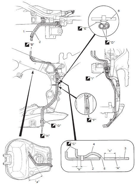
Fuel tank drain hose and breather hose routing diagram
|
 Set the
 Match the
 Arrange the
 Face the
 Set the
 Stick the
 Clamp the
 Pass the
 General description
Fuel injection system description
Fuel system
The fuel delivery system consists of the fuel tank (1), fuel pump (2), fuel
filter (3), fuel feed hose (4), fuel delivery pipes
(5) including fuel in ...
 Diagnostic information and procedures
Fuel system diagnosis
...
Other materials:
DTC “c41” (p0230-h/l): fp relay circuit
malfunction
Detected condition and possible cause
Detected condition
Possible cause
C41
No voltage is applied to fuel pump.
Fuel pump relay circuit open or short.
Fuel pump relay malfunction.
Fuel pump relay switch circuit is shorted to power
source.
...
Specifications
Tightening torque specifications
Note
the specified tightening torque is described in the following.
“Rear view mirror construction”
Reference: for the tightening torque of fastener not specified in this
section, refer to “tightening torque list” in section 0c . ...
Carrying a passenger
Before you invite someone to be a
passenger on your motorcycle,
you need to be thoroughly familiar
with motorcycle operation. Adjust
tire pressures and suspension
according to the tire pressure
and loading section and the suspension
section of this manual.
The passenger should always
hold ...