Suzuki GSX-R 1000 Service Manual: General description
Fuel injection system description
Fuel system
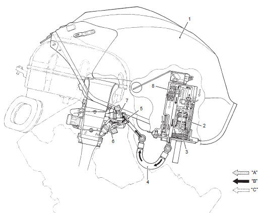
The fuel delivery system consists of the fuel tank (1), fuel pump (2), fuel filter (3), fuel feed hose (4), fuel delivery pipes (5) including fuel injectors (6) and (7), fuel pressure regulator (8). There is no fuel return hose. The fuel in the fuel tank is pumped up by the fuel pump and pressurized fuel flows into the injectors installed in the fuel delivery pipe. Fuel pressure is regulated by the fuel pressure regulator. As the fuel pressure applied to the fuel injectors (the fuel pressure in the fuel delivery pipe) is always kept at absolute fuel pressure of approx. 294 Kpa (2.9 Kgf/cm2, 41.8 Psi), the fuel is injected into the throttle body in conic dispersion when the injector opens according to the injection signal from the ecm.
The fuel relieved by the fuel pressure regulator flows back to the fuel tank.
|
 Precautions
Keep away from fire or spark.
During disassembling, use care to minimize spillage of
gasoline.
Spilled gasoline should be wiped off immediately.
...
 Schematic and routing diagram
Fuel tank drain hose and breather hose routing diagram
Fuel tank water drain hose
Fuel tank breather hose no. 1
Fuel tank breather hose no. 2
Fuel tank breather hose n ...
Other materials:
Throttle body disassembly and assembly
Refer to “throttle body removal and installation” .
Disassembly
Caution
identify the position of each removed part.
Organize the parts in their respective groups
so that they can be reinstalled in their
original positions.
Disconnect the fuel feed hose (1), isc valve ho ...
Wiring harness routing diagram
Wiring harness no. 2
Tapping clamp
: insert the clamp from the front side. Place the turn signal
and position light couplers in front of the clamp.
Steel clamp
: clamp the wiring harness at the blue taping point. Bend
the steel clamps to the front side.
...
Ecm / various sensors
Since each component is a high-precision part, great
care should be taken not to apply any severe impacts
during removal and installation.
Be careful not to touch the electrical terminals of the
electronic parts (ecm, etc.). The static electricity from
your body may damage them. ...