Suzuki GSX-R 1000 Service Manual: Steering / steering damper removal and installation
Removal steering damper
- Turn the ignition switch off.
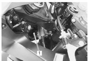
- Disconnect the steering damper solenoid coupler (1).
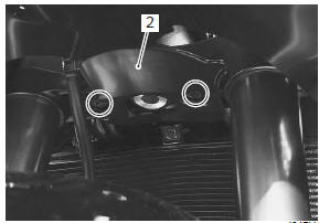
- Remove the lower bracket cover (2).
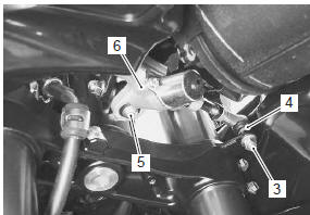
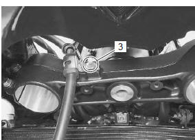
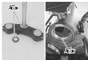
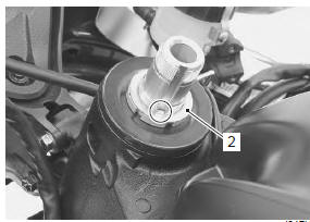
- Remove the steering damper mounting nut (3) while holding the lock-nut (4).
- Remove the steering damper mounting bolt (5).
- Remove the steering damper (6).
Steering
- Support the motorcycle with a jack or wooden block.
| Caution do not work by using side stand. Do not support the motorcycle with exhaust pipe. Make sure that the motorcycle is supported securely. |
- Remove the front wheel assembly. Refer to “front wheel assembly removal and installation” in section 2d .
- Remove the front forks. Refer to “front fork removal and installation” in section 2b .
- Remove the steering damper. Refer to “steering / steering damper removal and installation” .
- Lift and support the fuel tank. Refer to “fuel tank removal and installation” in section 1g (page 1g- 9).
- Remove the air cleaner box. Refer to “air cleaner box removal and installation” in section 1d .
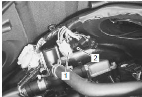
- Disconnect the ignition switch lead wire coupler (1) and immobilizer antenna lead wire coupler (for e- 02, 19, 24, 51) (2).
- Remove the brake hose clamp bolt (3).
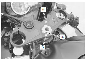
- Remove the steering stem head nut (4) and washer (5).
- Remove the steering stem upper bracket assembly (6).
| Note it is not necessary to remove the ignition switch from the upper bracket when servicing the steering system. |
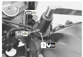
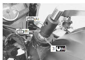
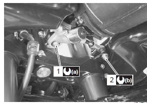
- Remove the steering stem lock-nut (7), washer and steering stem nut (8) with the special tools
| Note when loosening the stem nuts, hold the steering stem lower bracket to prevent it from falling. |
Special tool
 (a): 09940–14911 (steering stem nut
socket
wrench)
 (b): 09940–14960 (steering stem nut
socket
wrench)
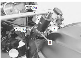
- Remove the steering stem lower bracket.
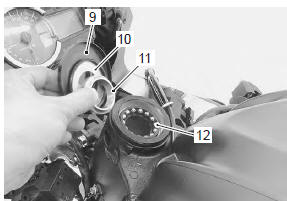
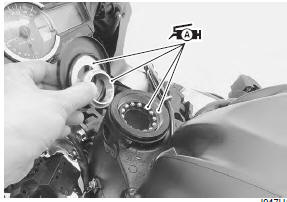
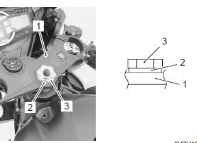
- Remove the dust seal cover (9), dust seal (10), upper bearing inner race (11) and upper bearing (12).
Installation
Install the steering in the reverse order of removal.
Pay attention to the following points:
Bearing
- Apply grease to the bearings, bearing races and dust seals before remounting the steering stem.
 : Grease 99000–25010 (suzuki
super
grease “a” or equivalent)
Steering stem nut
- Tighten the steering stem nut (1) to the specified torque with the special tools.
Special tool
 (a): 09940–14911 (steering stem nut
socket
wrench)
 (b): 09940–14960 (steering stem nut
socket
wrench)
Tightening torque steering stem nut (a): 45 n·m (4.5 Kgf-m, 32.5 Lbfft) then turn back 1/4 – 1/2
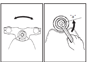
- Turn the steering stem lower bracket about five or six times to the left and right so that the angular ball bearings seat properly.
- Loosen the steering stem nut 1/4 – 1/2 turn “a”.
| Note this adjustment will vary from motorcycle to motorcycle. |
- When installing the washer (2), align the lug of the washer to the groove of the steering stem.
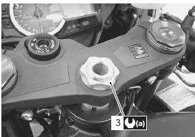
- Tighten the steering stem lock-nut (3) to the specified torque with the special tools.
Special tool
 (a): 09940–14911 (steering stem nut
socket
wrench)
 (b): 09940–14960 (steering stem nut
socket
wrench)
Tightening torque steering stem lock-nut (b): 80 n·m (8.0 Kgf-m, 58.0 Lbf-ft)
Steering stem upper bracket
Install the front forks and steering stem upper bracket in the following points:
- temporarily install the upper bracket (1), washer (2) and steering stem head nut (3). Refer to “handlebar removal and installation” .
- Temporarily install the front forks.
- Tighten the steering stem head nut (3) to the specified torque.
Tightening torque steering stem head nut (a): 90 n·m (9.0 Kgf-m, 65.0 Lbf-ft)
- Tighten the front fork upper and lower clamp bolts.
Refer to “front fork removal and installation” in section 2b .
Steering damper
- Apply grease to the bearings and dust seals.
 : Grease 99000–25010 (suzuki
super
grease “a” or equivalent)
- Install the steering damper and tighten the bolt (1) and nut (2).
Tightening torque steering damper bolt (a): 23 n·m (2.3 Kgf-m, 16.5 Lbf-ft) steering damper nut (b): 23 n·m (2.3 Kgf-m, 16.5 Lbf-ft)
Inspection after installation
- Check the steering tension. Refer to “steering tension adjustment” .
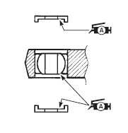
 Steering damper construction
Steering damper
Dust seal
Bearing
23 N·m (2.3 Kgf-m, 16.5 Lbf-ft)
Apply grease.
...
 Steering / steering damper related parts
inspection
Steering / steering damper related parts
inspection
Refer to “steering / steering damper removal and installation” .
Inspect the removed parts for the following
abnormalities:
Steering stem
Distortion of the steering stem and brackets.
...
Other materials:
Throttle body inspection and cleaning
Refer to “throttle body disassembly and assembly” .
Cleaning
Some
carburetor cleaning chemicals,
especially dip-type soaking solutions, are
very corrosive and must be handled carefully.
Always follow the chemical manufacturer’s
instructions on proper use, handling and
sto ...
Crankcase emission control system
description
The engine is equipped with a pcv system to prevent discharging crankcase
emissions into the atmosphere. Blow-by
gas in the engine is constantly drawn into the crankcase, which is returned to
the combustion chamber through the
pcv (breather) hose, air cleaner and throttle body.
...
Throttle body disassembly and assembly
Refer to “throttle body removal and installation” .
Disassembly
Caution
identify the position of each removed part.
Organize the parts in their respective groups
so that they can be reinstalled in their
original positions.
Disconnect the fuel feed hose (1), isc valve ho ...