Suzuki GSX-R 1000 Service Manual: Clutch lifter pin inspection and adjustment
Refer to “clutch removal” and “clutch installation” .
| Note when inspection and adjusting the clutch lifter pin, it is not necessary to install the clutch onto the countershaft. |
Inspect and adjust the clutch lifter pin in the following procedures:
- assemble the following parts into the primary driven gear assembly.
- Clutch sleeve hub
- spring washer seat, spring washer
- clutch drive plates, clutch driven plates
- pressure plate
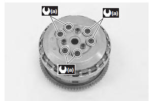
- clutch springs, clutch springs set bolts
Tightening torque clutch spring set bolt (a): 10 n·m (1.0 Kgf-m, 7.0 Lbf-ft)
| Note tighten the clutch spring set bolt little by little and diagonally. |
- Remove the clutch assembly from the primary driven gear assembly.
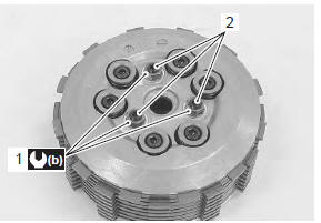
- Inspect the height “a” of clutch lifter pin at three positions using the thickness gauge. If the measurement is out of the specification, adjust the height “a” as shown in the figure.
Special tool
 : 09900–20803 (thickness gauge)
Clutch lifter pin height “a” standard: 0.2 – 0.4 Mm (0.008 – 0.016 In)
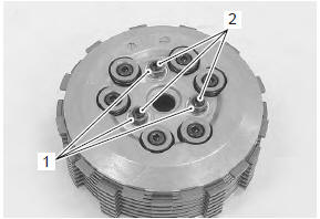
- Loosen the lock-nuts (1) and turn out the clutch lifter pin (2).
| Note each clutch lifter pin height should be as closely as possible. |
- Set the thickness gauge to 0.3 Mm (0.012 In).
Special tool
 (a): 09900–20803 (thickness gauge)
- Place a proper flat plate on the thickness gauges and hold them by hand.
- Slowly turn in the clutch lifter pin (2) until resistance is felt.
- Tighten the lock-nut (1).
Tightening torque clutch lifter pin lock-nut (b): 23 n·m (2.3 Kgf-m, 16.5 Lbf-ft)
 Clutch parts inspection
Refer to “clutch removal” and “clutch installation” .
Clutch drive and driven plate
Note
wipe off the engine oil from the drive and
driven plates with a clean rag.
Measure t ...
 Specifications
Service data
Clutch
unit: mm (in)
Tightening torque specifications
Note
the specified tightening torque is described in the following.
“Clutch control system components”&nbs ...
Other materials:
Isc valve reset
When removing or replacing the throttle body assembly,
reset the isc valve learned value in the following
procedures:
turn the ignition switch on position.
Set up the sds tools. (Refer to the sds operation
manual for further details.)
Click “active control”.
Click “is ...
Engine coolant temperature indicator light inspection
Inspect the engine coolant temperature meter and indicator light (led) in the
following procedures:
remove the left side cowling. Refer to “exterior parts removal and
installation” in section 9d .
Disconnect the ect sensor coupler (1).
Connect a variable resistor (2) ...
Generator inspection
Generator coil resistance
Remove the left side cowling. Refer to “exterior parts removal and
installation” in section 9d .
Disconnect the generator coupler (1).
Measure the resistance between the three lead
wires.
If the resistance is out of specified value, replace the
...