Suzuki GSX-R 1000 Service Manual: Component location
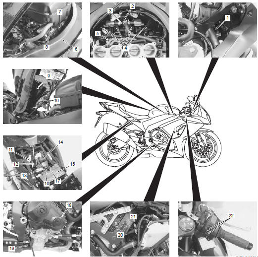
Electrical components location
|
 Country and area codes
The following codes stand for the applicable country(-ies) and area(-s).
Wire color symbols
Warning, caution and information labels location
Noise label
Information ...
 Specifications
Specifications
Note
these specifications are subject to change without notice.
Dimensions and dry mass
Engine
Drive train
Chassis
Electrical
Capacities
...
Other materials:
Front brake caliper disassembly and
assembly
Refer to “front brake caliper removal and installation” .
Note
the right and left calipers are installed
symmetrically and therefore the disassembly
procedure for one side is the same as that for
the other side.
Disassembly
Remove the brake pads (1) and spring from the
...
Cushion rod bearing removal and installation
Removal
Remove the cushion rod. Refer to “cushion rod removal and installation”
.
Remove the cushion rod bearing with the special
tool.
Special tool
(a):
09921–20240 (bearing remover set)
Installation
Caution
the removed bearings must be replaced with
new on ...
Break-in
The first 800 km (500 miles) is the
most important in the life of your
motorcycle. Proper operation during
this break-in period will help
assure maximum life and performance
from your new motorcycle.
The following guidelines explain
proper break-in procedures.
Maximum engine speed recommen ...