Suzuki GSX-R 1000 Service Manual: Gearshift shaft / gearshift cam plate removal and installation
Removal
- Remove the engine sprocket cover. Refer to “engine sprocket removal and installation” in section 3a .
- Remove the clutch components. Refer to “clutch removal” in section 5c .
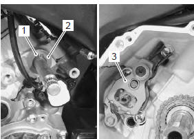
- Remove the snap ring (1) and washer (2) from the gearshift shaft.
Special tool
 : 09900–06107 (snap ring remover
(open
type))
- Remove the gearshift shaft assembly (3).
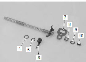
- Remove the following parts from the gearshift shaft.
Special tool
 : 09900–06107 (snap ring remover
(open
type))
|
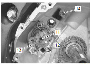
- Remove the gearshift cam plate bolt (11) and gearshift cam plate (12).
- Remove the gearshift cam stopper (13).
- Remove the gearshift arm stopper (14).
Installation
Install the gearshift shaft and gearshift cam plate in the reverse order of removal. Pay attention to the following points:
| Caution the removed snap rings must be replaced with new ones. |
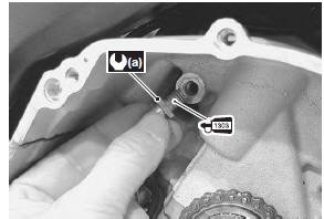
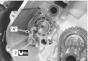
- Apply a small quantity of thread lock to the gearshift arm stopper and tighten it to the specified torque.
 : Thread lock cement
99000–32030
(thread lock cement super “1303” or
equivalent)
Tightening torque gearshift arm stopper (a): 19 n·m (1.9 Kgf-m, 13.5 Lbf-ft)
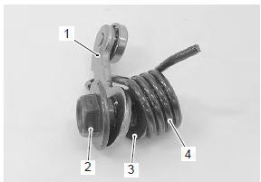
- Assemble the gearshift cam stopper (1), bolt (2), washer (3) and return spring (4).
- Tighten the gearshift cam stopper bolt (2) to the specified torque.
| Note hook the return spring end “a” to the stopper. |
Tightening torque gearshift cam stopper bolt (b): 10 n·m (1.0 Kgfm, 7.0 Lbf-ft)
- Check the gearshift cam stopper moves smoothly.
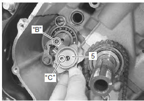
- Locate the gearshift cam in the neutral position.
- Install the gearshift cam plate (5).
| Note align the gearshift cam pin “b” with the gearshift cam plate hole “c”. |
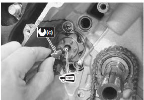
- Apply a small quantity of thread lock to the gearshift cam plate bolt and tighten it to the specified torque.
 : Thread lock cement
99000–32110
(thread lock cement super “1322” or
equivalent)
Tightening torque gearshift cam plate bolt (c): 13 n·m (1.3 Kgf-m, 9.5 Lbf-ft)
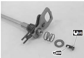
- Apply a small quantity of thread lock to the gearshift shaft end screw and tighten it to the specified torque.
 : Thread lock cement
99000–32110
(thread lock cement super “1322” or
equivalent)
Tightening torque gearshift shaft end screw (d): 8.5 N·m (0.85 Kgfm, 6.0 Lbf-ft)
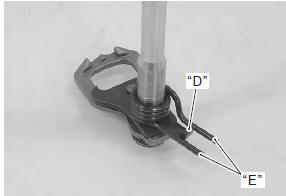
- When installing the gearshift shaft return spring, position the stopper “d” of gearshift arm between the shaft return spring ends “e”.
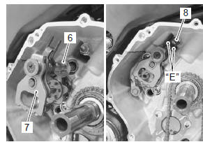
- Install the washer (6) and gearshift shaft assembly (7).
| Note pinch the gearshift arm stopper (8) with return spring ends “e”. |
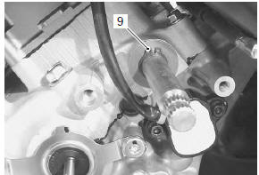
- Install a new snap ring (9).
Special tool
 : 09900–06107 (snap ring remover
(open
type))
- After installing the gearshift lever, check the gearshift lever height. Refer to “gearshift lever height inspection and adjustment” .
 Gearshift shaft construction
Gearshift shaft
Washer
Snap ring
Gearshift shaft return spring
Gearshift cam drive plate
Gearshift plate return spring
8.5 N·m (0.85 Kgf-m,
6.0 Lb ...
 Gearshift linkage inspection
Refer to “gearshift shaft / gearshift cam plate removal and installation” .
Gearshift shaft
Check the gearshift shaft for bend or wear.
Check the return spring for damage or fatigue.
If any de ...
Other materials:
Air bleeding from brake fluid circuit
Air trapped in the brake fluid circuit acts like a cushion to
absorb a large proportion of the pressure developed by
the master cylinder and thus interferes with the full
braking performance of the brake caliper. The presence
of air is indicated by “sponginess” of the brake lever and
also by la ...
DTC “c46” (p1657-h/l or p1658): excv
actuator circuit malfunction
Detected condition
Possible cause
C46
The operation signal does not reach the
excv actuator.
Excva position sensor voltage low or
high
0.14 V ≤ Sensor voltage < 4.9 V
(without the above range)
excva can not operate properly.
Excva ...
Noise emission control system description
Tampering with the noise control system prohibited: local law or federal law
prohibits the following
acts or the causing thereof:
the removal or rendering inoperative by any person, other than for
purposes of maintenance, repair or
replacement, of any device or element of design in ...