Suzuki GSX-R 1000 Service Manual: Cushion rod bearing removal and installation
Removal
- Remove the cushion rod. Refer to “cushion rod removal and installation” .
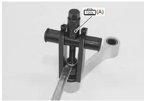
- Remove the cushion rod bearing with the special tool.
Special tool

(a):
09921–20240 (bearing remover set)
Installation
| Caution the removed bearings must be replaced with new ones. |
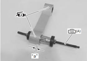
- Press the bearings into the cushion rod at 0.5 Mm (0.02 In) depth “a” from the cushion rod side surface with the special tool and suitable size socket wrench.
| Note when installing the bearing, apply a small quantity of the grease to housing. |
 : Grease 99000–25010 (suzuki
super
grease “a” or equivalent)
Special tool
(a): 09924–84521 (bearing
installer set)
|
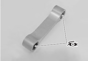
- Apply grease to the bearings.
: Grease 99000–25010 (suzuki
super
grease “a” or equivalent)
- Install the cushion rod. Refer to “cushion rod bearing removal and installation” .
 Cushion rod inspection
Refer to “cushion rod removal and installation” .
Collar and spacer
Remove the collar and spacer from the cushion rod.
Inspect the collar and spacer for any flaws or other
damage. If an ...
 Swingarm removal and installation
Removal
Cut the drive chain. Refer to “drive chain replacement” in section 3a .
Remove the rear wheel assembly. Refer to “rear wheel assembly removal
and installation” in section 2d .
...
Other materials:
Light bulb replacement
The wattage rating of each bulb is
shown in the following chart.
When replacing a burned-out
bulb, always use the same wattage
rating according to the following
chart.
Caution
Using a light bulb with the
wrong wattage rating can
cause electrical system damage
or shorte ...
Radiator cap inspection
Inspect the radiator cap in the following procedures:
remove the radiator cap. Refer to “cooling circuit inspection” .
Attach the radiator cap (1) to the radiator tester (2)
as shown.
Slowly apply pressure to the radiator cap.
If the radiator cap does not hold the pre ...
Headlight
To replace the headlight bulbs,
perform the following steps:
Upper light bulb
Remove the bolt 1 to lift the
instrument panel 2.
Turn the cap 3 counterclockwise
and remove it.
Unhook the bulb holder spring
4 and pull out the socket 5.
Pull off the bulb from ...