Suzuki GSX-R 1000 Service Manual: DTC “c41” (p0230-h/l): fp relay circuit malfunction
Detected condition and possible cause
|
Detected condition |
Possible cause |
||
|
C41 |
No voltage is applied to fuel pump. |
|
|
|
P0230 |
H |
Voltage is applied to fuel pump although fuel pump relay is turned off. | |
|
L |
No voltage is applied to fuel pump although fuel pump relay is turned on. | ||
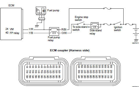
Wiring diagram
Troubleshooting
| Caution when using the multi-circuit tester, do not strongly touch the terminal of the ecm coupler with a needle pointed tester probe to prevent terminal damage. |
| Note after repairing the trouble, clear the dtc using sds tool. Refer to “use of sds diagnosis reset procedures” . |
C41 (use of mode select switch)
|
Step |
Action |
Yes |
No |
|
1 |
Is the fp relay ok? |
|
Replace the fp relay with a new one. |
P0230-h (use of sds)
|
Step |
Action |
Yes |
No |
|
1 |
Is the fp relay ok? |
|
Replace the fp relay with a new one. |
P0230-l (use of sds)
|
Step |
Action |
Yes |
No |
|
1 |
Is the fp relay ok? |
|
Replace the fp relay with a new one. |
 DTC “c40” (p0505 / p0506 / p0507): isc
valve circuit malfunction
DTC “c40” (p0505 / p0506 / p0507): isc
valve circuit malfunction
Detected condition and possible cause
Detected condition
Possible cause
C40/P0505
The circuit voltage of motor drive is
unusual.
Isc valve circuit open or ...
 DTC “c41” (p2505): ecm power input signal
malfunction
DTC “c41” (p2505): ecm power input signal
malfunction
Detected condition and possible cause
Detected condition
Possible cause
C41/P2505
No voltage is applied to the ecm.
Lead wire/coupler connection of ecm t ...
Other materials:
Water pump components
Impeller
Mechanical seal
Oil seal
O-ring
O-ring
8
N·m (0.8 Kgf-n, 6.0 Ib-ft)
10 N·m
(1.0 Kgf-n, 7.0 Ib-ft)
6 N·m (0.6
Kgf-n, 4.5 Ib-ft)
13 N·m
(1.3 Kgf-n, 9.5 Ib-ft)
Apply grease.
Apply engine coolant.
Apply molyb ...
Evaporative emission control system
removal and installation (only for e-33)
Hose
removal
Lift and support the fuel tank. Refer to “fuel tank
removal and installation” in section 1g (page 1g-
9).
Remove the frame cover assembly. Refer to “exterior parts removal and
installation” in section 9d .
Remove the evap hoses as shown in the evap canister h ...
Side-stand removal and installation
Removal
Support the motorcycle with a jack or wooden block.
Caution
do not support the motorcycle with the exhaust pipes.
Make sure that the motorcycle is supported securely.
Remove the side-stand as shown in the side-stand construction.
Refer to ...