Suzuki GSX-R 1000 Service Manual: DTC “c41” (p2505): ecm power input signal malfunction
Detected condition and possible cause
|
Detected condition |
Possible cause |
|
|
C41/P2505 |
No voltage is applied to the ecm. |
|
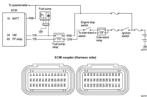
Wiring diagram
Troubleshooting
| Caution when using the multi-circuit tester, do not strongly touch the terminal of the ecm coupler with a needle pointed tester probe to prevent terminal damage. |
| Note after repairing the trouble, clear the dtc using sds tool. Refer to “use of sds diagnosis reset procedures” . |
|
Step |
Action |
Yes |
No |
|
1 |
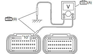
Special tool Tester knob indication voltage ( ) Ecm input voltage battery voltage ((+) terminal: “10” – (–) terminal: ground) Ecm couplers (harness side)
Is the voltage ok? |
|
Open or short circuit in the r/bl wire. |
 DTC “c41” (p0230-h/l): fp relay circuit
malfunction
DTC “c41” (p0230-h/l): fp relay circuit
malfunction
Detected condition and possible cause
Detected condition
Possible cause
C41
No voltage is applied to fuel pump.
Fuel pump relay circuit open or short.
...
 DTC “c42” (p1650): ig switch circuit
malfunction
DTC “c42” (p1650): ig switch circuit
malfunction
Detected condition and possible cause
Detected condition
Possible cause
Ignition switch signal is not input to the ecm.
Ignition system circuit open or short.
...
Other materials:
Troubleshooting
This troubleshooting guide is provided
to help you find the cause of
some common complaints.
Caution
Failure to troubleshoot a problem
correctly can damage your
motorcycle. Improper repairs
or adjustments may damage
the motorcycle instead of fixing
it. Such damage may ...
Pair system inspection
Pair hose
Lift and support the fuel tank with the prop stay.
Refer to “fuel tank removal and installation” in section 1g .
Remove the air cleaner box. Refer to “air cleaner box removal and
installation” in section 1d .
Inspect the pair hoses for wear or damage. If it is worn or da ...
Specifications
Service data
Electrical
Tightening torque specifications
Note
the specified tightening torque is described in the following.
“Wiring harness routing diagram”
Reference: for the tightening torque of fastener not specified in this
section, refer to “tightening torque l ...