Suzuki GSX-R 1000 Service Manual: DTC “c44” (p0130/p0135): ho2 sensor (ho2s) circuit malfunction
Detected condition and possible cause
|
Detected condition |
Possible cause |
|
| C44/P0130 | Ho2 sensor output voltage is not input to
ecm during engine operation and running
condition. Sensor voltage > 1.0 V |
|
| C44/P0135 | The heater can not operate so that heater operation voltage is not supplied to the oxygen heater circuit. | |
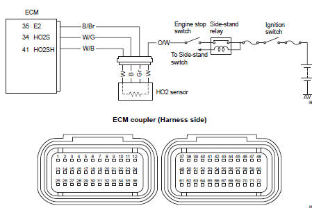
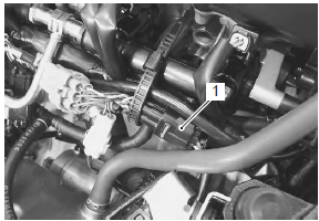
Wiring diagram
Troubleshooting (when indicating c44/p0130:)
| Caution when using the multi-circuit tester, do not strongly touch the terminal of the ecm coupler with a needle pointed tester probe to prevent terminal damage. |
| Note after repairing the trouble, clear the dtc using sds tool. Refer to “use of sds diagnosis reset procedures” . |
|
Step |
Action |
Yes |
No |
|
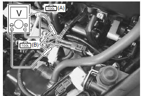
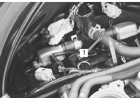
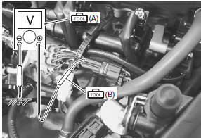
1 |
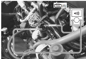
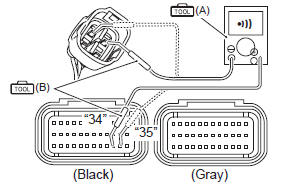
Special tool Tester knob indication
continuity test (
Special tool Tester knob indication
continuity ( Ecm couplers (harness side)
Is the continuity ok? |
Go to step 2. | W/g wire shorted to the power source, or w/g or b/br wire open. |
|
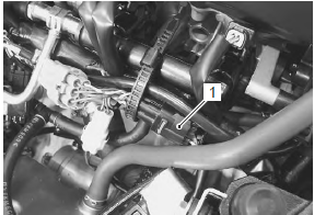
2 |
Special tool Tester knob indication
voltage ( Ho2 sensor output voltage at idle speed 0.3 V and less ((+) terminal: w/g (b) – (–) terminal: b/br (gr))
Ho2 sensor output voltage at 5 000 r/min 0.6 V and more ((+) terminal: w/g – (–) terminal: b/br) Is the voltage ok? |
|
Replace the ho2
sensor with a new one. Refer to “ho2 sensor removal and installation” in section 1c . |
 (a): 09900–25008 (multi
 )
)
 (a): 09900–25008 (multi
 (b): 09900–25009
 )
)
Troubleshooting (when indicating c44/p0135:)
| Note after repairing the trouble, clear the dtc using sds tool. Refer to “use of sds diagnosis reset procedures” . |
|
Step |
Action |
Yes |
No |
|
|
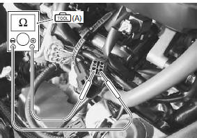
1 |
Special tool Tester knob indication resistance (Ω) Ho2 sensor heater resistance 6.7 – 9.5 Ω at 23 °c (73 °f) (w – w)
Is the resistance ok? |
Go to step 2. | Replace the ho2
sensor with a new one. Refer to “ho2 sensor removal and installation” in section 1c . |
|
|
2 |
Special tool Tester knob indication
voltage ( Heater voltage battery voltage ((+) terminal: w/b – (–) terminal: ground)
Is the voltage ok? |
|
|
 (a): 09900–25008 (multi
 (a): 09900–25008 (multi
 (b): 09900–25009
 )
)
 DTC “c42” (p1650): ig switch circuit
malfunction
DTC “c42” (p1650): ig switch circuit
malfunction
Detected condition and possible cause
Detected condition
Possible cause
Ignition switch signal is not input to the ecm.
Ignition system circuit open or short.
...
 DTC “c46” (p1657-h/l or p1658): excv
actuator circuit malfunction
DTC “c46” (p1657-h/l or p1658): excv
actuator circuit malfunction
Detected condition
Possible cause
C46
The operation signal does not reach the
excv actuator.
Excva position sensor voltage low or
high
0.14 V ≤ Sensor v ...
Other materials:
Exhaust system components
Exhaust pipe gasket
Exhaust pipe assembly
Ho2 sensor
Connector
: install the connector so that the
chamfer side faces backward.
Muffler chamber
Muffler body
Excv cable no. 1
Excv cable no. 2
When loosening or tightening the pulley bol ...
Evaporative emission control system
inspection (only for e-33)
Refer to “evaporative emission control system removal and installation (only
for e-33)” .
Hose
Inspect the hoses for wear or damage. If it is worn or
damage, replace the hose with a new one.
Note
make sure that the hoses are securely
connected.
Evap canister
Inspect the eva ...
Water hose removal and installation
Removal
Remove the side cowlings. Refer to “exterior parts
removal and installation” in section 9d (page 9d-
6).
Drain engine coolant. Refer to “cooling system inspection” in section
0b .
Lift and support the fuel tank. Refer to “fuel tank
removal and installation” in se ...