
Suzuki GSX-R 1000 Service Manual: DTC “c60” (p0480): cooling fan relay circuit malfunction
Detected condition and possible cause
|
Detected condition |
Possible cause |
| Cooling fan relay signal is not input to ecm. |
|
Wiring diagram
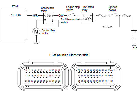
Troubleshooting
| Caution when using the multi-circuit tester, do not strongly touch the terminal of the ecm coupler with a needle pointed tester probe to prevent terminal damage. |
| Note after repairing the trouble, clear the dtc using sds tool. Refer to “use of sds diagnosis reset procedures” . |
|
Step |
Action |
Yes |
No |
|
1 |
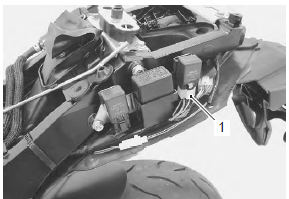
Is the cooling fan relay ok? |
|
Replace the cooling fan relay with a new one. |
Active control inspection
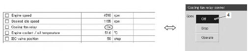
- Set up the sds tool. (Refer to sds operation manual for further details.)
- Start the engine and run it in idling condition.
- Click “cooling fan relay control” (1).
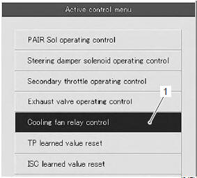
- Click the “operate” (2).
At this time, if an operation sound is heard from the cooling fan relay and cooling fan motors are operated, the function is normal.
| Note the cooling fan relay and cooling fan motor inspection is operational at any engine coolant temperature until reaching 100 °c (212 °f). In a hot engine condition with the intake air temperature exceeding 40 °c (104 °f), however, the engine coolant temperature at which the inspection is operational will be restricted to 95 °c (203 °f). |

- Click the “stop” (3) to check the operation properly.
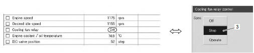
- Click the “off” (4) to check the cooling fan relay and cooling fan motor operation.
Note
|
 DTC “c49” (p1656): pair control solenoid
valve circuit malfunction
DTC “c49” (p1656): pair control solenoid
valve circuit malfunction
Detected condition and possible cause
Detected condition
Possible cause
Pair control solenoid valve voltage is not input to ecm
Pair control solenoid valve circ ...
 DTC “c62” (p0443): evap system purge
control solenoid valve circuit malfunction
(e-33 only)
DTC “c62” (p0443): evap system purge
control solenoid valve circuit malfunction
(e-33 only)
Detected condition and possible cause
Detected condition
Possible cause
Evap system purge control valve voltage is not input to
ecm.
Evap system purge contro ...
Other materials:
Starter button inspection
Inspect the starter button in the following procedures:
remove the air cleaner box. Refer to “air cleaner box removal and
installation” in section 1d .
Disconnect the right handlebar switch coupler (1).
Inspect the starter button for continuity with the
tester.
If ...
Clutch lifter pin inspection and adjustment
Refer to “clutch removal” and “clutch installation” .
Note
when inspection and adjusting the clutch
lifter pin, it is not necessary to install the
clutch onto the countershaft.
Inspect and adjust the clutch lifter pin in the following
procedures:
assemble the ...
To sensor removal and installation
Removal
Remove the ap sensor. Refer to “ap sensor removal and installation” .
Disconnect the coupler (1) and remove the to
sensor (2).
Installation
Install the to sensor in the reverse order of removal.
Pay attention to the following point:
when installing the to s ...