Suzuki GSX-R 1000 Service Manual: Heated oxygen sensor (ho2s) removal and installation
Removal
 Do not Do not
remove the ho2 sensor while it is hot. |
Caution
|
- Lift and support the fuel tank with the prop stay.
Refer to “fuel tank removal and installation” in section 1g .
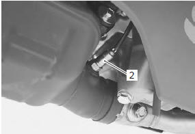
- Disconnect the ho2 sensor coupler (1).
- Remove the ho2 sensor (2).
Installation
Install the ho2 sensor in the reverse order of removal.
Pay attention to the following points:
| Caution do not apply oil or other materials to the sensor air hole. |
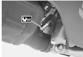
- Tighten the ho2 sensor to the specified torque.
Tightening torque ho2 sensor (a): 25 n·m (2.5 Kgf-m, 18.0 Lbf-ft)
Heated oxygen sensor (ho2s) inspection
Refer to “dtc “c44” (p0130/p0135): ho2 sensor (ho2s) circuit malfunction” in section 1a (page 1a- 103).

 Pair reed valve removal and installation
Removal
Lift and support the fuel tank with the prop stay.
Refer to “fuel tank removal and installation” in section 1g .
Remove the air cleaner box. Refer to “air cleaner box removal and ...
Other materials:
Tp reset
When replacing the throttle body assembly or tp sensor
with a new one or reinstalling the tp sensor, reset the
tp learned value in the following procedures:
Note
keep the throttle valves fully closed while
resetting the tp learned value.
Turn the ignition switch on.
...
Front brake caliper disassembly and
assembly
Refer to “front brake caliper removal and installation” .
Note
the right and left calipers are installed
symmetrically and therefore the disassembly
procedure for one side is the same as that for
the other side.
Disassembly
Remove the brake pads (1) and spring from the
...
Special tools and equipment
Recommended service material
Note
required service material is also described in the following.
“Rear brake components”
Special tool
...