
Suzuki GSX-R 1000 Service Manual: Ignition coil inspection
Refer to “electrical components location” in section 0a .
Ignition coil primary peak voltage
- Remove the air cleaner box. Refer to “air cleaner box removal and installation” in section 1d .
- Disconnect all ignition coil. Refer to “ignition coil and spark plug removal and installation” .
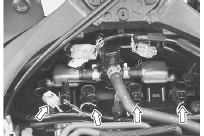
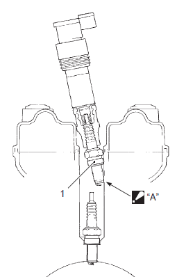
- Connect the new spark plugs to each ignition coil.
- Connect all the ignition coil lead wire couplers to the ignition coil respectively, and ground them on the cylinder head (each spark plug hole).
| Caution avoid grounding the spark plugs and suppling the electrical shock to the cylinder head cover (magnesium parts) to prevent the magnesium material from damage. |
| Note be sure that all the spark plugs are connected properly and the battery used is in fully-charged condition. |
|
 Contact
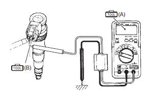
- Insert the needle pointed probe to the lead wire coupler.
| Caution use the special tool to prevent the rubber of the water proof coupler from damage. |
- Connect the multi-circuit tester with the peak voltage adaptor as follows.
| Caution before using the multi-circuit tester and peak voltage adaptor, refer to the appropriate instruction manual. |
Special tool
 (a): 09900–25008 (multi circuit
tester set)
 (b): 09900–25009 (needle-point
probe set)
Tester knob indication: voltage (
)
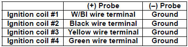
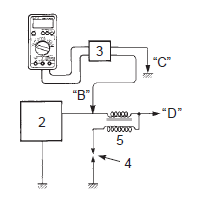
|
- Measure the ignition coil primary peak voltage in the following procedures:
 Do not Do not
touch the tester probes and spark plugs to prevent an electric shock while testing. |
- Shift the transmission into neutral, turn the ignition switch on and grasp the clutch lever.
- press the starter button and allow the engine to crank for a few seconds, and then measure the ignition coil primary peak voltage.
- Repeat the b) procedure several times and measure
the highest peak voltage.
If the voltage is lower than standard range, inspect the ignition coil and the ckp sensor.
Ignition coil primary peak voltage 80 v and more
- After measuring the ignition coil primary peak voltage, reinstall the removed parts.
Ignition coil resistance
- Remove the ignition coil. Refer to “ignition coil and spark plug removal and installation” .
- Measure the ignition coil for resistance in both primary and secondary coils. If the resistance is not within the standard range, replace the ignition coil with a new one.
Special tool
(a): 09900–25008 (multi circuit
tester set)
Tester knob indication resistance (Ω)
Ignition coil resistance primary: 1.1 – 1.9 Ω ((+) terminal – (–) terminal) secondary: 6.4 – 9.6 KΩ (spark plug cap – (–) terminal)
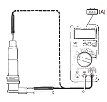
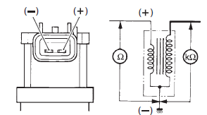
- After measuring the ignition coil resistance, reinstall the removed parts.
 Ignition coil and spark plug removal and
installation
Ignition coil and spark plug removal and
installation
Removal
The hot
engine can burn you.
Wait until the engine is cool enough to touch.
Turn the ignition switch off.
Remove the air cleaner box. Refer to “air cleaner box ...
 Ckp sensor inspection
Refer to “electrical components location” in section 0a .
Ckp sensor peak voltage
Lift and support the fuel tank. Refer to “fuel tank
removal and installation” in section 1g (page 1g-
9).
D ...
Other materials:
Swingarm related parts inspection
Refer to “swingarm removal and installation” (page 2c-
9).
Spacers
Remove the collar and spacer from the swingarm.
Inspect the collars and spacer for wear and damage.
If any defects are found, replace them with new
ones.
Chain buffer
Inspect the chain buffer for wear and ...
Ecm / various sensors
Since each component is a high-precision part, great
care should be taken not to apply any severe impacts
during removal and installation.
Be careful not to touch the electrical terminals of the
electronic parts (ecm, etc.). The static electricity from
your body may damage them. ...
Excva removal and installation
Removal
Turn the ignition switch off.
Remove the left side cowling. Refer to “exterior parts removal and
installation” in section 9d .
Connect the special tool (mode select switch) to the dealer mode
coupler. Refer to “self-diagnostic procedures” in section 1a .
After tur ...