Suzuki GSX-R 1000 Service Manual: Precautions
Precautions for clutch system
Refer to “general precautions” in section 00 (page 00-1).
Schematic and routing diagram
Clutch cable routing diagram
Refer to “throttle cable routing diagram” in section 1d .
Diagnostic information and procedures
Clutch system symptom diagnosis
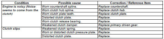
 Clutch
...

Other materials:
Specifications
Service data
Fi sensors
Tightening torque specifications
Reference: for the tightening torque of fastener not specified in this
section, refer to “tightening torque list” in section 0c . ...
Cooling system inspection
Inspect cooling system
every 6 000 km (4 000 miles, 6 months)
Replace engine coolant
every 2 years
Engine coolant level inspection
Hold the motorcycle vertically.
Check the engine coolant level by observing the “f” and “l” lines on
the engine coolant reservoir tank. If the level i ...
Specifications
Service data
Suspension
unit: mm (in)
Tightening torque specifications
Note
the specified tightening torque is described in the following.
“Rear suspension components” “rear suspension assembly
construction”
Reference: for the tightening torque of fastener ...