Suzuki GSX-R 1000 Service Manual: Schematic and routing diagram
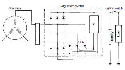
Charging system diagram
Component location
Charging system components location
Refer to “electrical components location” in section 0a .
 Charging system
...

Other materials:
Engine coolant
Coolant level
The engine coolant solution
should be between "f" (full) and
"1..:' (Low) level lines on the engine
coolant reservoir. If the level is
lower than "1..:' (Low) level line,
bring it up to "f" (full) level by adding
50:50 mixture of distilled water ...
Diagnostic information and procedures
Drive chain and sprocket symptom diagnosis
Condition
Possible cause
Correction / reference item
Noisy drive chain
Worn sprocket
Replace
Worn drive chain
Replace
Stretched drive chain
Replace
Too large drive chain slack
Adju ...
Starter button inspection
Inspect the starter button in the following procedures:
remove the air cleaner box. Refer to “air cleaner box removal and
installation” in section 1d .
Disconnect the right handlebar switch coupler (1).
Inspect the starter button for continuity with the
tester.
If ...