Suzuki GSX-R 1000 Service Manual: Self-diagnostic procedures
Use of mode select switch
Note
|
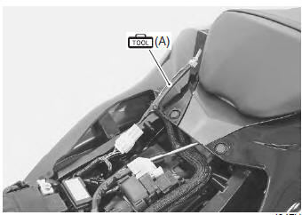
- Remove the front seat. Refer to “exterior parts removal and installation” in section 9d (page 9d- 6).
- Connect the special tool to the mode select switch coupler.
Special tool
 (a): 09930–82720 (mode selection
switch)
- Start the engine or crank the engine for more than 4 seconds.
- Turn the special tool’s switch on.
- Check the dtc to determine the malfunction part.
Refer to “dtc table” .
Special tool
(a): 09930–82720 (mode selection
switch)
- After repairing the trouble, turn off the ignition switch and turn on again. If dtc is indicated (c00), the malfunction is cleared.
Note
|
- Turn the ignition switch off and disconnect the special tool from the mode select switch coupler.
- Reinstall the front seat.
Use of sds
Note
|
- Remove the front seat. Refer to “exterior parts removal and installation” in section 9d (page 9d- 6).
- Set up the sds tools. (Refer to the sds operation manual for further details.)
Special tool
 (a): 09904–41010 (suzuki diagnostic
system set)
 (b): 99565–01010–020 (cd-rom
ver.20)
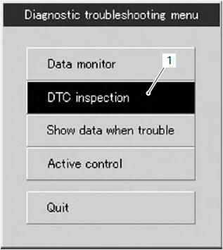
- Click the dtc inspection button (1).
- Start the engine or crank the engine for more than 4 seconds.
- Check the dtc to determine the malfunction part.
Refer to “dtc table” .
Note
|
- After repairing the trouble, clear to delete history code (past dtc). Refer to “use of sds diagnosis reset procedures” .
- Close the sds tool and turn the ignition switch off.
- Disconnect the sds tool and install the front seat.

 Use of sds diagnosis reset procedures
Note
the malfunction code is memorized in the
ecm also when the lead wire coupler of any
sensor is disconnected. Therefore, when a
lead wire coupler has been disconnected at
the ...
Other materials:
Special tools and equipment
Recommended service material
Note
required service material is also described in the following.
“Exhaust system components”
Special tool
...
Storage procedure
If your motorcycle is to be left
unused for an extended period of
time, it needs special servicing
requiring appropriate materials,
equipment and skill. For this reason,
suzuki recommends that you
trust this maintenance work to
your suzuki dealer. If you wish to
service the machine for stora ...
Front wheel related parts inspection
Refer to “front wheel assembly removal and installation” .
Tire
Refer to “tire inspection” in section 0b .
Front brake disc
Refer to “front brake disc inspection” in section 4b .
Dust seal
Inspect the lip of dust seals for wear or damage. If any
defects are found, replace the dust seal ...