Suzuki GSX-R 1000 Service Manual: Transmission related parts inspection
Refer to “transmission removal” , “transmission installation” and “countershaft gear / driveshaft gear disassembly and assembly” .
Gearshift fork to groove clearance
| Note the clearance for each gearshift fork plays an important role in the smoothness and positiveness of the shifting action. |
Using the thickness gauge, check the gearshift fork clearance in the groove of its gear.
If the clearance checked is noted to exceed the limit specified, replace the fork or its gear, or both.
Special tool
 (a): 09900–20803 (thickness gauge)
Gearshift fork to gearshift fork groove clearance standard: 0.1 – 0.3 Mm (0.004 – 0.012 In) service limit: 0.5 Mm (0.02 In)
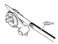
Gearshift fork groove width
Measure the gearshift fork groove width using the vernier calipers.
Special tool
 (a): 09900–20102 (vernier calipers
(200 mm))
Gearshift fork groove width standard: 5.0 – 5.1 Mm (0.197 – 0.201 In)
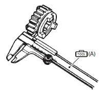
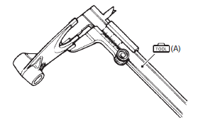
Gearshift fork thickness
Measure the gearshift fork thickness using the vernier calipers.
Special tool
 (a): 09900–20102 (vernier calipers
(200 mm))
Gearshift fork thickness standard: 4.8 – 4.9 Mm (0.189 – 0.193 In)
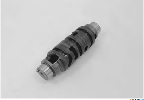
Gearshift cam
Inspect the gearshift cam groove for abnormal wear and damage. If any defects are found, replace the gearshift cam with a new one.
Gearshift cam bearing
Inspect the gearshift cam bearings, left and right for abnormal noise and smooth rotation.
Replace the bearing if there is anything unusual. Refer to “transmission removal” and “transmission installation” .
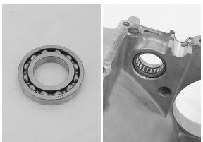
Driveshaft bearing
Inspect the driveshaft left bearing for abnormal noise and smooth rotation while it is in the case.
Replace the bearing if there is anything unusual. Refer to “transmission removal” and “transmission installation” .
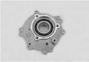
Inspect the driveshaft right bearing for abnormal noise and smooth rotation.
If there is anything unusual, replace the bearing assembly. Refer to “transmission removal” and “transmission installation” .
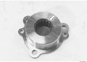
Driveshaft oil seal
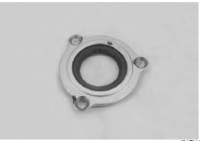
Inspect the driveshaft left bearing dust seal for wear and damage.
Replace the dust seal if there is anything unusual. Refer to “transmission removal” and “transmission installation” .
Gear position (gp) switch inspection
Refer to “side-stand / ignition interlock system parts inspection” in section 1i .
 Countershaft gear / driveshaft gear
disassembly and assembly
Refer to “transmission removal” and “transmission installation” .
Disassembly
Caution
identify the position of each removed part.
Organize the parts in their respective groups
...
 Gear position (gp) switch removal and installation
Removal
Turn the ignition switch off.
Lift and support the fuel tank. Refer to “fuel tank
removal and installation” in section 1g (page 1g-
9).
Disconnect the gear position swi ...
Other materials:
Schematic and routing diagram
Fuel tank drain hose and breather hose routing diagram
Fuel tank water drain hose
Fuel tank breather hose no. 1
Fuel tank breather hose no. 2
Fuel tank breather hose no. 3
3-Way joint
Frame
White marking
Set the
hose end to the root of tank nippl ...
Special tools and equipment
Special tool
...
Rear shock absorber adjustment
After installing the rear suspension, adjust the spring
pre-load and damping force as follows:
Spring pre-load adjustment
The set length 179.3 Mm (7.06 In) provides the
maximum spring pre-load.
The set length 189.3 Mm (7.45 In) provides the
minimum spring pre-load.
Std position
184.3 ...
