Suzuki GSX-R 1000 Service Manual: Cushion lever removal and installation
Removal
- Remove the right side cowling and side frame covers. Refer to “exterior parts removal and installation” in section 9d .
- Support the motorcycle with a jack to relieve load on the cushion levers.
- Remove the left muffler and muffler chamber heat guard no. 2. Refer to “muffler / muffler chamber / exhaust pipe removal and installation” in section 1k .
- Remove the rear shock absorber. Refer to “rear shock absorber removal and installation” .
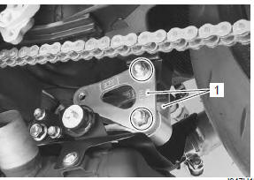
- Remove the cushion levers (1).
Installation
Install the cushion levers in the reverse order of removal.
Pay attention to the following point:
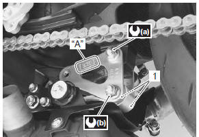
- set the cushion levers so that the arrow mark “a” points forward.
- Install the washers (1) between the cushion rod and cushion levers.
- Tighten each nut to the specified torque.
Tightening torque cushion lever mounting nut (a): 98 n·m (9.8 Kgfm, 71.0 Lbf-ft) cushion rod rear mounting nut (b): 98 n·m (9.8 Kgf-m, 71.0 Lbf-ft)
- Install the rear shock absorber. Refer to “rear shock absorber removal and installation” .
- Install the muffler chamber heat guard no. 2 And left muffler. Refer to “muffler / muffler chamber / exhaust pipe removal and installation” in section 1k .
- Install the side frame covers and right side cowling.
Refer to “exterior parts removal and installation” in section 9d .
 Rear shock absorber disposal
Refer to “rear shock absorber removal and installation” .
The rear shock absorber unit contains high-pressure
nitrogen gas.
Mishandling can cause explosion.
Keep away from f ...
 Cushion lever inspection
Refer to “cushion lever removal and installation” .
Cushion lever
Inspect the cushion levers for damage. If any defects are
found, replace the cushion levers with new ones.
...
Other materials:
Foreword
This manual contains an introductory description on the suzuki gsx-r1000 and
procedures for its inspection/
service and overhaul of its main components.
Other information considered as generally known is not included.
Read the general information section to familiarize yourself with the mot ...
Specifications
Service data
Suspension
unit: mm (in)
Tightening torque specifications
Note
the specified tightening torque is described in the following.
“Rear suspension components” “rear suspension assembly
construction”
Reference: for the tightening torque of fastener ...
Precautions
Precautions for suspension
Refer to “general precautions” in section 00 (page 00-1).
All
suspensions, bolts and nuts are an important part in that it could
affect the performance of vital
parts. They must be tightened to the specified torque periodically and
if the suspension ...