
Suzuki GSX-R 1000 Service Manual: Cushion rod removal and installation
Removal
- Remove the right side cowling and side frame covers. Refer to “exterior parts removal and installation” in section 9d .
- Support the motorcycle with a jack to relieve load on the cushion rod.
- Remove the muffler chamber. Refer to “muffler / muffler chamber / exhaust pipe removal and installation” in section 1k .
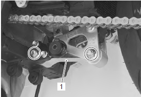
- Remove the cushion rod (1) and washer.
Installation
Install the cushion rod in the reverse order of removal.
Pay attention to the following points:
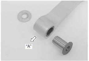
- before installing the cushion rod to the frame, insert the collar into the bearing from the left side.
- Install the washer between the cushion rod right side and frame.
|
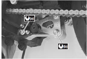
- Tighten each bolts and nuts to the specified torque.
Tightening torque cushion rod front mounting nut (a): 98 n·m (9.8 Kgf-m, 71.0 Lbf-ft) cushion rod rear mounting nut (b): 98 n·m (9.8 Kgf-m, 71.0 Lbf-ft)
- Install the muffler chamber. Refer to “muffler / muffler chamber / exhaust pipe removal and installation” in section 1k .
- Install the side frame covers and right side cowling.
Refer to “exterior parts removal and installation” in section 9d .
 Cushion lever inspection
Refer to “cushion lever removal and installation” .
Cushion lever
Inspect the cushion levers for damage. If any defects are
found, replace the cushion levers with new ones.
...
 Cushion rod inspection
Refer to “cushion rod removal and installation” .
Collar and spacer
Remove the collar and spacer from the cushion rod.
Inspect the collar and spacer for any flaws or other
damage. If an ...
Other materials:
Clutch removal
Drain engine oil. Refer to “engine oil and filter replacement” in
section 0b .
Lift and support the fuel tank with the prop stay.
Refer to “fuel tank removal and installation” in section 1g .
Disconnect the ckp sensor coupler (1).
Remove the clutch cover (2).
...
Clutch cable removal and installation
Removal
Remove the left side cowling. Refer to “exterior parts removal and
installation” in section 9d .
Disconnect the clutch cable from the clutch lever.
Refer to “handlebar removal and installation” in section 6b .
Remove the clutch cable as shown in the throttle cable ro ...
Specifications
Service data
Wattage
unit: w
Tightening torque specifications
Note
the specified tightening torque is described in the following.
“Rear lighting system construction” “license plate light
components” “reflex reflector construction”
Reference: for the ...