Suzuki GSX-R 1000 Service Manual: Engine assembly installation
Install the engine in the reverse order of engine removal.
Pay attention to the following points:
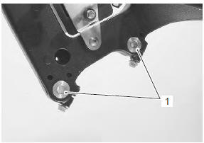
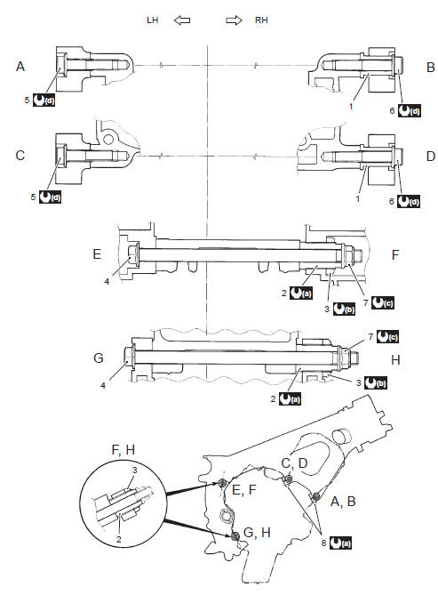
- before installing the engine, install the collars (1).
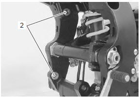
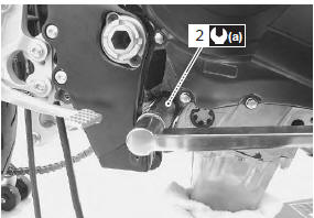
- Before installing the engine, install the engine mounting thrust adjusters (2).
- Gradually raise the rear side of the engine assembly, and then put the drive chain on the driveshaft.
| Caution be careful not to catch the wiring harness between the frame and the engine. |
- Install all engine mounting bolts and tighten them temporarily.
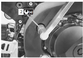
- Tighten the engine mounting thrust adjusters (2) to the specified torque.
Tightening torque engine mounting thrust adjuster (a): 23 n·m (2.3 Kgf-m, 16.5 Lbf-ft)
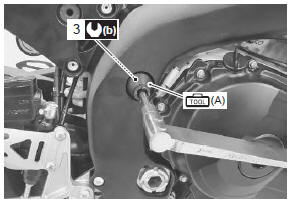
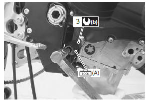
- Tighten the engine mounting thrust adjuster lock-nuts (3) to the specified torque with the special tool.
Tightening torque engine mounting thrust adjuster lock-nut (b): 45 n·m (4.5 Kgf-m, 32.5 Lbf-ft)
Special tool
 (a): 09940–14990 (engine mounting
adjust
wrench)
- Tighten all engine mounting bolts and nuts to the specified torque, as shown in the following illustration
| Note the engine mounting nuts are self-locking. Once the nuts have been removed, they are no longer of any use. |
- Tighten the engine mounting pinch bolt to the specified torque, as shown in the following illustration.
|
 23
23
 45 N·m (4.5
 75 N·m (7.5
 55 N·m (5.5
- Install the engine sprocket. Refer to “engine sprocket removal and installation” in section 3a .
- Install the exhaust pipe assembly and muffler. Refer to “muffler / muffler chamber / exhaust pipe removal and installation” in section 1k .
- Install the radiator. Refer to “radiator / cooling fan motor removal and installation” in section 1f .
- Install the throttle body. Refer to “throttle body removal and installation” .
- Install the air cleaner box. Refer to “air cleaner box removal and installation” .
- After remounting the engine, route the wiring harness, cable and hoses properly. Refer to “wiring harness routing diagram” in section 9a , “throttle cable routing diagram” and “water hose routing diagram” in section 1f .
- Pour engine coolant and engine oil. Refer to “cooling system inspection” in section 0b and “engine oil and filter replacement” in section 0b .
- After finishing the engine installation, check the following items.
- Throttle cable play refer to “throttle cable play inspection and adjustment” in section 0b .
- Throttle valve synchronization refer to “throttle valve synchronization” (page 1d- 16).
- Clutch cable play refer to “clutch cable play inspection and adjustment” in section 0b .
- Drive chain slack refer to “drive chain inspection and adjustment” in section 0b .
- Engine oil and coolant leakage refer to “cooling circuit inspection” in section 1f .
 Engine assembly removal
Before taking the engine out of the frame, wash the
engine using a steam cleaner. Engine removal is
sequentially explained in the following steps:
remove the side cowlings. Refer to “exter ...
 Engine top side disassembly
It is unnecessary to remove the engine assembly from
the frame when servicing the cylinder head cover and
camshafts.
Note
before servicing the engine top side
components (until camshaf ...
Other materials:
DTC “c21” (p0110-h/l): iat sensor circuit
malfunction
Detected condition and possible cause
Detected condition
Possible cause
C21
Output voltage is not with in the following
range.
0.15 V ≤ Sensor voltage < 4.85 V
Iat sensor circuit open or short.
Iat sensor malfunction.
Ec ...
Steering system inspection
Inspect steering system
initially at 1 000 km (600 miles, 2 months) and every
12 000 km (7 500 miles, 24 months) thereafter
Steering should be adjusted properly for smooth turning
of handlebars and safe running. Overtighten steering
prevents smooth turning of the handlebars and too loose
steer ...
Crankcase breather (pcv) hose / reed
valve / cover removal and installation
Removal
Lift and support the fuel tank with the prop stay.
Refer to “fuel tank removal and installation” in section 1g .
Remove the air cleaner box. Refer to “air cleaner box removal and
installation” in section 1d .
Disconnect the crankcase breather (pcv) hose (1).
...