Suzuki GSX-R 1000 Service Manual: Engine assembly removal
Before taking the engine out of the frame, wash the engine using a steam cleaner. Engine removal is sequentially explained in the following steps:
- remove the side cowlings. Refer to “exterior parts removal and installation” in section 9d (page 9d- 6).
- Remove the front seat. Refer to “exterior parts removal and installation” in section 9d (page 9d- 6).
- Disconnect the battery (–) lead wire (1).
- Jack up the motorcycle and fix it for safety.
- Drain engine oil. Refer to “engine oil and filter replacement” in section 0b .
- Drain engine coolant. Refer to “engine oil and filter replacement” in section 0b .
- Lift and support the fuel tank. Refer to “fuel tank removal and installation” in section 1g (page 1g- 9).
- Remove the air cleaner box. Refer to “air cleaner box removal and installation” .
- Remove the throttle body assembly. Refer to “throttle body removal and installation” (page 1d- 10).
- Remove the oil cooler and hoses. Refer to “oil cooler / oil cooler hose removal and installation” in section 1e .
- Remove the radiator assembly. Refer to “radiator / cooling fan motor removal and installation” in section 1f .
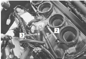
- Disconnect the water/air bleed hose (2) and radiator inlet hose (3).
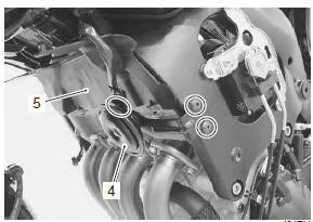
- Remove the horn (4) and radiator heat guard (5).
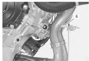
- Remove the radiator/oil cooler mounting bracket (6).
- Remove the exhaust system components. Refer to “muffler / muffler chamber / exhaust pipe removal and installation” in section 1k .
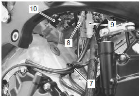
- Remove the clamp (7).
- Disconnect the oil pressure switch lead wire coupler (8), generator lead wire coupler (9) and ect sensor coupler (10).
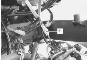
- Disconnect the gp switch lead wire coupler (11).
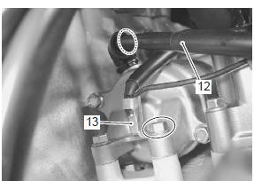
- Disconnect the starter motor lead wire (12) and engine ground lead wire (13).
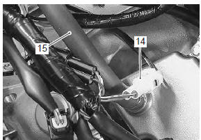
- Disconnect the ckp sensor lead wire coupler (14).
- Remove the crankcase breather (pcv) hose (15).
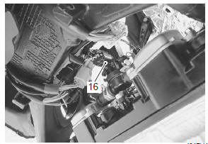
- Disconnect the pair solenoid valve coupler (16).
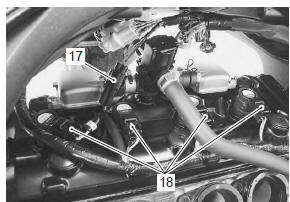
- Disconnect the cmp sensor lead wire coupler (17) and ignition coil couplers (18).
- Remove the ignition coils.
Caution
|
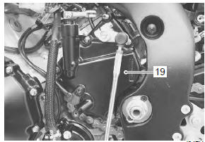
- Remove the engine sprocket cover (19). Refer to “engine sprocket removal and installation” in section 3a .
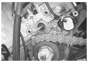
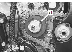
- Remove the dowel pins and clutch push rod (20).
- Remove the engine sprocket (21). Refer to “engine sprocket removal and installation” in section 3a .
- Support the engine using an engine jack.
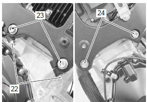
- Loosen the engine mounting pinch bolts (22) (rh).
- Remove the engine mounting bolts (23) (rh).
- Remove the engine mounting bolts (24) (lh).
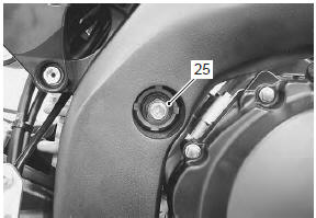
- Remove the engine mounting nut (25).
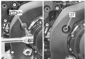
- Remove the engine mounting thrust adjuster locknut (26) with the special tool.
- Loosen the engine mounting thrust adjuster (27) fully.
Special tool
 (a): 09940–14990 (engine mounting
adjust
wrench)
| Note do not remove the engine mounting bolt at this stage. |
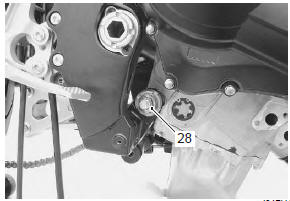
- Remove the engine mounting nut (28).
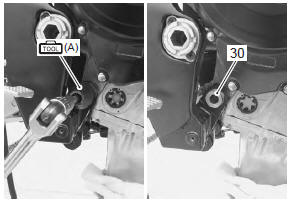
- Loosen the engine mounting thrust adjuster lock-nut (29) with the special tool.
- Loosen the engine mounting thrust adjuster (30) fully.
Special tool
 (a): 09940–14990 (engine mounting
adjust
wrench)
| Note do not remove the engine mounting bolt at this stage. |
- Remove the engine mounting bolts and gradually lower the front side of the engine. Then, take off the drive chain from the driveshaft.
- Remove the engine assembly.
 Tp reset
When replacing the throttle body assembly or tp sensor
with a new one or reinstalling the tp sensor, reset the
tp learned value in the following procedures:
Note
keep the throttle valves ...
 Engine assembly installation
Install the engine in the reverse order of engine removal.
Pay attention to the following points:
before installing the engine, install the collars (1).
Before installing the en ...
Other materials:
Dtc “c36” (p1764), “c37” (p1765), “c38” (p1766) or “c39” (p1767): secondary
fuel injector circuit
malfunction
Detected condition and possible cause
Detected condition
Possible cause
Some failure exists in the fuel injector signal in a high
load, high revolution condition.
Injector circuit open or short.
Injector malfunction.
Ecm malfunction.
...
Ignition switch removal and installation
Removal
Remove the air cleaner box. Refer to “air cleaner box removal and
installation” in section 1d .
Disconnect the ignition switch lead wire coupler (1).
Disconnect the immobilizer lead wire coupler (2).
(For e-02, 19, 24, 51)
Remove the harness clamp (3).
...
Wiring diagram
Refer to “wire color symbols” in section 0a .
For e-02, 19, 24, 51
For e-03, 28
For e-14, 33
...