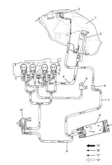
Suzuki GSX-R 1000 Service Manual: Evaporative emission control system diagram (only for e-33)
|
 Noise emission control system description
Tampering with the noise control system prohibited: local law or federal law
prohibits the following
acts or the causing thereof:
the removal or rendering inoperative by any person, other ...

Other materials:
Swingarm bearing removal and installation
Removal
Remove the swingarm. Refer to “swingarm removal and installation” .
Remove the swingarm pivot bearings (1) using the
special tool.
Special tool
(a):
09921–20240 (bearing remover set)
Remove the center spacer (2).
Remove the cushion lever bearing (3) usin ...
Carrying a passenger
Carrying a passenger, when done
correctly, is a great way to share
the joy of motorcycling. You will
have to alter your riding style
somewhat since the extra weight
of a passenger will affect handling
and braking. You may also need
to adjust tire pressures and suspension;
please refer to the ...
Oil pan / oil pressure regulator / oil strainer
removal and installation
Note
the oil pan/oil strainer/oil pressure regulator
cannot be serviced with the engine installed
in the frame.
Removal
Remove the engine assembly from the frame. Refer to “engine assembly
removal” in section 1d .
Remove the plate (1).
Remove the oil pan ...