Suzuki GSX-R 1000 Service Manual: Front fork removal and installation
| Note the right and left front forks are installed symmetrically and therefore the removal procedure for one side is the same as that for the other side. |
Removal
- Remove the front wheel. Refer to “front wheel assembly removal and installation” in section 2d .
Caution
|
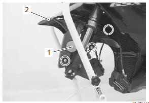
- Disconnect the brake hoses from the clamps on the front fender.
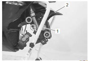
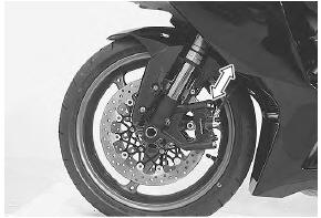
- Remove the reflex reflectors (1). (Except for e-02, 19, 51)
- remove the front fender (2) by removing the bolts
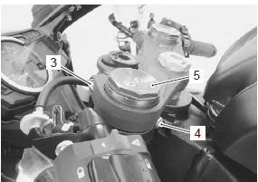
- Loosen the front fork upper clamp bolt (3).
- Loosen the handlebar clamp bolt (4).
| Note slightly loosen the front fork cap (5) to facilitate later disassembly. |
Special tool
 : 09941–53670 (front fork cap
socket
wrench (45 mm))
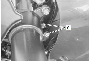
- Loosen the front fork lower clamp bolts (6) and remove the front fork.
| Note hold the front fork by hand to prevent it sliding out of the steering stem. |
Installation
- Set the front fork to the steering stem lower bracket temporarily by tightening the lower clamp bolts (1).
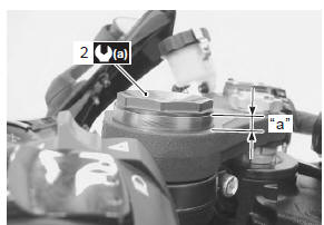
- Tighten the front fork cap (2) to the specified torque.
Tightening torque front fork cap (a): 35 n·m (3.5 Kgf-m, 25.5 Lbf-ft)
- Loosen the lower clamp bolts.
- Set the front fork with the edge of the outer tube positioned 7.0 Mm (0.28 In) “a” from the upper surface of the upper bracket.
|
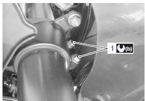
- Tighten the front fork lower clamp bolts (1).
Tightening torque front fork lower clamp bolt (b): 23 n·m (2.3 Kgfm, 16.5 Lbf-ft)
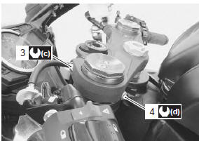
- Tighten the front fork upper clamp bolt (3).
Tightening torque front fork upper clamp bolt (c): 23 n·m (2.3 Kgfm, 16.5 Lbf-ft)
- Tighten the handlebar clamp bolt (4).
Tightening torque handlebar clamp bolt (d): 23 n·m (2.3 Kgf-m, 16.5 Lbf-ft)
- Install the front wheel. Refer to “front wheel assembly removal and installation” in section 2d .
 After After
remounting the brake calipers, pump the brake lever until the pistons push the pads correctly. |
| Note before tightening the front axle bolt and front axle pinch bolts, move the front fork up and down four or five times. |
 Front fork components
Front fork cap
O-ring
Rebound damping force adjuster rod
Compression damping force adjuster rod
Piston rod nut
O-ring
Piston ring
Rod guide case
Spr ...
 Front suspension adjustment
After installing the front fork, adjust the spring pre-load
and two kinds of damping force as follows:
Adjust the
left and right front forks to the
same setting.
Spring pre-load ...
Other materials:
Cooling system inspection
Inspect cooling system
every 6 000 km (4 000 miles, 6 months)
Replace engine coolant
every 2 years
Engine coolant level inspection
Hold the motorcycle vertically.
Check the engine coolant level by observing the “f” and “l” lines on
the engine coolant reservoir tank. If the level i ...
Generator inspection
Generator coil resistance
Remove the left side cowling. Refer to “exterior parts removal and
installation” in section 9d .
Disconnect the generator coupler (1).
Measure the resistance between the three lead
wires.
If the resistance is out of specified value, replace the
...
Throttle cable routing diagram
Throttle cable no. 1
Throttle cable no. 2
Clutch cablev
Front brake hose
Pass
the throttle cables in front of the front brake hose.
Pass the
clutch cable above the right air intake pipe.
Clamp the
clutch cable at the white taping point and m ...