Suzuki GSX-R 1000 Service Manual: Schematic and routing diagram
Ignition system diagram
Refer to “wire color symbols” in section 0a .
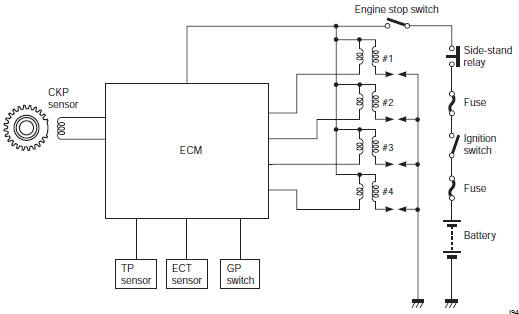
Ignition system components location
Refer to “electrical components location” in section 0a .
 Drive mode selector description
Engine power characteristics can be changed in 3
modes by operating the drive mode selector to meet
various riding conditions and rider’s preference.
Operation
Drive mode is preset at a-mode w ...

Other materials:
General description
Fuel injection system description
Fuel system
The fuel delivery system consists of the fuel tank (1), fuel pump (2), fuel
filter (3), fuel feed hose (4), fuel delivery pipes
(5) including fuel injectors (6) and (7), fuel pressure regulator (8). There is
no fuel return hose. The fuel in the fu ...
Symbols
Listed in the table below are the symbols indicating instructions and other
information necessary for servicing.
The meaning of each symbol is also included in the table.
Abbreviations
A:
abdc: after bottom dead center
ac: alternating current
acl: air cleaner, air cleaner box
api: ame ...
Engine bottom side assembly
Assemble the engine bottom side in the reverse order of
disassembly. Pay attention to the following points:
Note
apply engine oil to each running and sliding
part before reassembling.
Breather oil return plate
When installing the breather oil return plate (1), apply
thread loc ...