Suzuki GSX-R 1000 Service Manual: Side-stand / ignition interlock system parts inspection
Check the interlock system for proper operation. If the interlock system does not operate properly, check each component for damage or abnormalities. If any abnormality is found, replace the component with a new one.
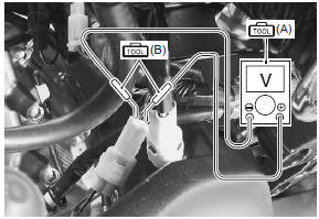
Side-stand switch
- Turn the ignition switch off.
- Remove the left side cowling. Refer to “exterior parts removal and installation” in section 9d .
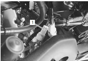
- Disconnect the side-stand switch coupler (1).
- Measure the voltage between g and b/w lead wires.
Special tool
 : 09900–25008 (multi circuit tester
set)
Tester knob indication
diode test ( )
)
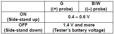
| Note if the tester reads 1.4 V and below when the tester probes are not connected, replace its battery. |
- Connect the side-stand switch coupler.
- Install the removed parts.
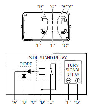
Turn signal / side-stand relay
The turn signal/side-stand relay is composed of the turn signal relay, side-stand relay and diode.
Side-stand relay
- Remove the turn signal/side-stand relay. Refer to “turn signal / side-stand relay removal and installation” .
- Check the insulation between “d” and “e” terminals using the multi-circuit tester.
- Apply 12 v to terminals “d” and “c” ((+) to “d” and (– ) to “c”) and check the continuity between “d” and “e”. If there is no continuity, replace the turn signal/ side-stand relay with a new one.
Special tool
 : 09900–25008 (multi circuit tester
set)
Tester knob indication
continuity test (  )
)
- Install the turn signal/side-stand relay. Refer to “turn signal / side-stand relay removal and installation” .
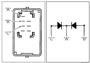
Diode inspection
- Remove the turn signal/side-stand relay. Refer to “turn signal / side-stand relay removal and installation” .
- Measure the voltage between the “a”, “b” and “c” terminals using the multi-circuit tester.
Special tool
 : 09900–25008 (multi circuit tester
set)
Tester knob indication
diode test (  )
)
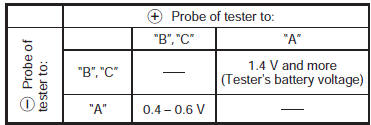
| Note if the multi circuit tester reads 1.4 V and below when the tester probes are not connected, replace its battery. |
- Install the turn signal/side-stand relay. Refer to “turn signal / side-stand relay removal and installation” .
Gear position switch
- Lift and support the fuel tank. Refer to “fuel tank removal and installation” in section 1g (page 1g- 9).
- Disconnect the gear position switch coupler (1).
| Caution when disconnecting and connecting the gear position switch coupler, make sure to turn off the ignition switch, or electronic parts may get damaged. |
- Check the continuity between bl and b lead wires with the transmission in “neutral”.
Special tool
 : 09900–25008 (multi circuit tester
set)
Tester knob indication
continuity test ( )
)

- Connect the gear position switch coupler to the wiring harness.
- Insert the needle pointed probes to the lead wire coupler.
- Turn the ignition switch on and side-stand to upright position.
- Measure the voltage between p and b/w lead wires using the multi-circuit tester when shifting the gearshift lever from low to top.
Special tool
(a): 09900–25008 (multi circuit
tester set)
 (b): 09900–25009 (needle-point
probe set)
Tester knob indication
voltage ( )
)
Gear position switch voltage (except neutral position) 0.6 V and more ((+) p – (–) b/w)
- Turn the ignition switch off.
- Install the removed parts.
 Turn signal / side-stand relay removal and
installation
Turn signal / side-stand relay removal and
installation
Removal
Turn the ignition switch off.
Remove the frame cover assembly. Refer to “exterior parts removal and
installation” in section 9d .
Remove the turn signal/side-stand relay ...
 Starter torque limiter removal and
installation
Starter torque limiter removal and
installation
Removal
Remove the clutch assembly. Refer to “clutch removal” in section 5c .
Remove the washer (1), starter idle gear no. 1 (2)
And starter torque limiter (3).
Installation
Inst ...
Other materials:
Front brake caliper parts inspection
Refer to “front brake caliper disassembly and assembly” .
Brake caliper cylinder
Inspect the brake caliper cylinder wall for nicks,
scratches or other damage. If any damage is found,
replace the caliper with a new one.
Brake caliper piston
Inspect the surface of brake caliper pistons for a ...
Exhaust control system description
The exhaust control system (excs) consists of the exhaust control valve (excv),
exhaust control valve actuator
(excva) and exhaust control valve cables (excv cables).
Excv is installed in the exhaust pipe. Excva is mounted inside of the right
frame. The excv is operated by the
excva via the ...
Steering system inspection
Inspect steering system
initially at 1 000 km (600 miles, 2 months) and every
12 000 km (7 500 miles, 24 months) thereafter
Steering should be adjusted properly for smooth turning
of handlebars and safe running. Overtighten steering
prevents smooth turning of the handlebars and too loose
steer ...