Suzuki GSX-R 1000 Service Manual: Tightening torque specifications
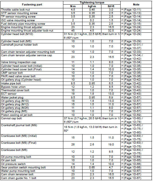
| Note the specified tightening torque is described in the following. “Throttle cable routing diagram” “throttle body components” “throttle body construction” “engine assembly installation” |
Reference
: for the tightening torque of fastener not specified in this section, refer to “tightening torque list” in section 0c .
 Service data
Valve + guide
unit: mm (in
Camshaft + cylinder head
unit: mm (in
Cylinder + piston + piston ring
unit: mm (in)
Conrod + crankshaft
unit: mm (in)
Balancer
unit: mm (in)
Th ...
 Special tools and equipment
Recommended service material
Note
required service material is also described in the following.
“Throttle body components” “engine bottom side assembly”
Special tool
...
Other materials:
Excva removal and installation
Removal
Turn the ignition switch off.
Remove the left side cowling. Refer to “exterior parts removal and
installation” in section 9d .
Connect the special tool (mode select switch) to the dealer mode
coupler. Refer to “self-diagnostic procedures” in section 1a .
After tur ...
Drive chain adjustment
Inspect the drive chain slack
before each use of the motorcycle.
Place the motorcycle on the
side stand. The drive chain
should be adjusted for 20 - 30
mm (0.8 - 1.2 In) of slack, as
shown.
Warning
Too much chain slack can
cause the chain to come off the
sprockets, resul ...
Noise emission control system description
Tampering with the noise control system prohibited: local law or federal law
prohibits the following
acts or the causing thereof:
the removal or rendering inoperative by any person, other than for
purposes of maintenance, repair or
replacement, of any device or element of design in ...