Suzuki GSX-R 1000 Service Manual: Crankshaft thrust clearance inspection and selection
Refer to “engine bottom side disassembly” (page 1d- 49).
Refer to “engine bottom side assembly” .
Inspection
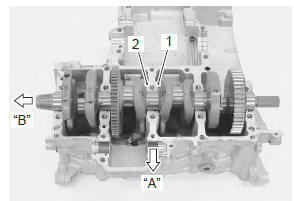
- With the crankshaft’s right-side and left-side thrust bearings inserted into the upper crankcase.
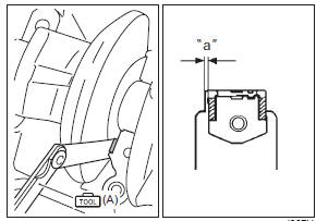
- Measure the thrust clearance “a” between the leftside thrust bearing and crankshaft using the thickness gauge. If the thrust clearance exceeds the standard range, adjust the thrust clearance.
| Note pull the crankshaft to the left (generator side) so that there is no clearance on the right-side thrust bearing. |
Special tool
 : 09900–20803 (thickness gauge)
Crankshaft thrust clearance “a” standard: 0.060 – 0.110 Mm (0.0024 – 0.0043 In)
|
Selection
- Remove the right-side thrust bearing and measure its thickness using the micrometer. If the thickness of the right-side thrust bearing is below standard, replace it with a new bearing and measure the thrust clearance again, as described in inspection 1) and 2).
Special tool
 (a): 09900–20205 (micrometer (0 – 25
mm))
Right-side thrust bearing thickness standard: 2.420 – 2.440 Mm (0.0953 – 0.0961 In)
- If the right-side thrust bearing is within the standard range, reinsert the right-side thrust bearing and remove the left-side thrust bearing.
- With the left-side thrust bearing removed, measure the clearance “a” using the thickness gauge as shown.
Special tool
 (b): 09900–20803 (thickness gauge)
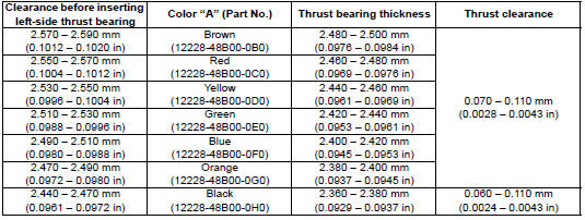
- Select a left-side thrust bearing from the selection table.
| Note right-side thrust bearing has the same specification as the green (12228-48b00-0e0) of left-side thrust bearing. |
Thrust bearing selection table
|
- After selecting a left-side thrust bearing, install it and then measure the thrust clearance again.
 Crankshaft journal bearing inspection and
selection
Crankshaft journal bearing inspection and
selection
Refer to “engine bottom side disassembly” (page 1d-
49).
Refer to “engine bottom side assembly” .
Inspection
Inspect each upper and lower crankcase bearing for
any damage.
Set ...
 Specifications
...
Other materials:
Location of parts
ciutch lever
left handlebar switches
indicator lights
tachometer
ignition switch
front brake fluid reservoir
right handlebar switches
throttle grip
front brake lever
fuel tank cap
front suspension spring pre-load and rebound damping
force ...
Throttle body components
Fuel delivery pipe
Fuel delivery pipe t-joint
O-ring
Tp sensor
Stp sensor
Secondary fuel injector
Primary fuel injector
Cushion seal
Isc valve
Air screw
Vacuum hose
Evap system purge control solenoid valve
For e-33 only
3.5
...
Valve guide replacement
Remove the cylinder head. Refer to “engine top side disassembly” .
Remove the valves. Refer to “cylinder head disassembly and assembly” .
Using the valve guide remover, drive the valve guide
out toward the intake or exhaust camshaft side.
Special tool
(a): 09916–43211 (valve ...