Suzuki GSX-R 1000 Service Manual: Cylinder identification
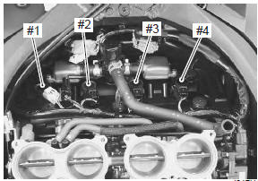
The four cylinders of this engine are identified as #1, 2, 3 and #4 cylinder, as counted from left to right (as viewed by the rider on the seat).
 Break-in procedures
During manufacture only the best possible materials are
used and all machined parts are finished to a very high
standard but it is still necessary to allow the moving parts
to “break-in” before sub ...
 Country and area codes
The following codes stand for the applicable country(-ies) and area(-s).
Wire color symbols
Warning, caution and information labels location
Noise label
Information ...
Other materials:
Cam chain tensioner inspection
Inspect the cam chain tensioner in the following
procedures:
remove the cam chain tensioner. Refer to “cam chain guide / cam chain
tensioner removal and installation” .
Check the contacting surface of the cam chain
tensioner. If it is worn or damaged, replace it with a
new ...
Rear wheel related parts inspection
Refer to “rear wheel assembly removal and installation” .
Tire
Refer to “tire inspection” in section 0b .
Rear brake disc
Refer to “rear brake disc inspection” in section 4c .
Wheel damper
Refer to “drive chain related parts inspection” in section 3a .
Sprocket
Refer to “drive chain ...
Front brake hose routing diagram
Hose clamp
: clamp end should face downward.
Stopper
: after the brake hose union has contacted to the stopper, tighten
the union bolt.
Hose guide
: pass the brake hose through the hose guide.
Stopper
: after positioning the clamp with the stopper ...