Suzuki GSX-R 1000 Service Manual: DTC “c91” (p0500): vehicle speed sensor circuit malfunction
Detected condition and possible cause
|
Detected condition |
Possible cause |
| Speedometer does not receive signal from the vehicle speed sensor for more than 6 sec. When the motorcycle is running. Ecm does not receive signal from the vehicle speed sensor for more than 6 sec. When the motorcycle is running. Failure in communication between ecm and speedometer with reference to vehicle speed. |
|
Wiring diagram
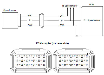
Troubleshooting
| Caution when using the multi-circuit tester, do not strongly touch the terminal of the ecm coupler with a needle pointed tester probe to prevent terminal damage. |
| Note after repairing the trouble, clear the dtc using sds tool. Refer to “use of sds diagnosis reset procedures” . |
|
Step |
Action |
Yes |
No |
|
|
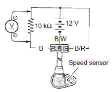
1 |
Special tool Tester knob indication
voltage (
Is the voltage ok? |
|
|
 (a): 09900–25008 (multi
 )
)
 DTC “c62” (p0443): evap system purge
control solenoid valve circuit malfunction
(e-33 only)
DTC “c62” (p0443): evap system purge
control solenoid valve circuit malfunction
(e-33 only)
Detected condition and possible cause
Detected condition
Possible cause
Evap system purge control valve voltage is not input to
ecm.
Evap system purge contro ...
 DTC “c93” (p1769): steering damper
solenoid valve circuit malfunction
DTC “c93” (p1769): steering damper
solenoid valve circuit malfunction
Detected condition and possible cause
Detected condition
Possible cause
C93
Steering damper control current does not flow to
the solenoid valve. With ig turned on ...
Other materials:
Specifications
Service data
Fi sensors
Tightening torque specifications
Reference: for the tightening torque of fastener not specified in this
section, refer to “tightening torque list” in section 0c . ...
Battery removal and installation
Removal
Remove the front seat. Refer to “exterior parts
removal and installation” in section 9d (page 9d-
6).
Disconnect the battery (–) lead wire (1).
Disconnect the battery (+) lead wire (2).
Note
be sure to disconnect the battery (–) lead
wire (1) first, th ...
Front wheel assembly removal and installation
Removal
Remove the brake calipers, left and right.
Caution
do not operate the brake lever with the
caliper removed.
Loosen two axle pinch bolts (1) on the right front fork
leg.
Remove the front axle bolt (2).
Raise the front wheel off the ground a ...