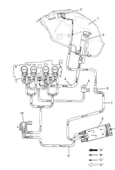
Suzuki GSX-R 1000 Service Manual: Evaporative emission control system diagram (only for e-33)
Suzuki GSX-R 1000 Service Manual / Engine / Emission control devices / General description / Evaporative emission control system
diagram (only for e-33)
|
 Noise emission control system description
Tampering with the noise control system prohibited: local law or federal law
prohibits the following
acts or the causing thereof:
the removal or rendering inoperative by any person, other ...

Other materials:
Steering damper maintenance
Keep the steering damper
shaft 1 clean at all times.
Wipe off any oil residue with a
cloth.
Do not confuse the grease-like
residue on the steering damper's
shaft with an oil leak. Collection of
this residue is normal and is from
oil seal lubricant used in the
damper.
Yo ...
Drive chain cleaning and
oiling
Clean and oil the chain as follows:
Wash the chain with kerosene.
Kerosene will lubricate and
clean the chain.
Warning
Kerosene can be hazardous .
Kerosene is flammable. Children
or pets may be harmed
from contact with kerosene.
Keep flames and smoking
mater ...
© 2011-2026 Copyright www.suzukigsxr.org