Suzuki GSX-R 1000 Service Manual: Ignition switch removal and installation
Removal
- Remove the air cleaner box. Refer to “air cleaner box removal and installation” in section 1d .
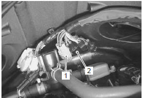
- Disconnect the ignition switch lead wire coupler (1).
- Disconnect the immobilizer lead wire coupler (2).
(For e-02, 19, 24, 51)
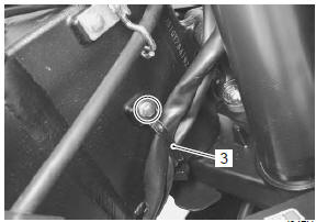
- Remove the harness clamp (3).
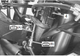
- Remove the ignition switch (4) with the special tools.
Special tool
 (a): 09930–11920 (torx bit (jt40h))
(b): 09930–11940 (torx bit holder)
(a): 09930–11920 (torx bit (jt40h))
(b): 09930–11940 (torx bit holder)
Installation
Install the ignition switch in the reverse order of removal.
Pay attention to the following points:
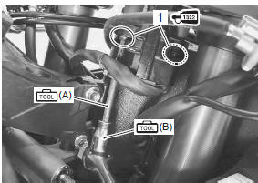
- tighten the ignition switch mounting bolts (1), right and left with the special tools.
| Caution when reusing the ignition switch bolts, clean the threaded part and apply a thread lock to them. |
Special tool
(a): 09930–11920 (torx bit (jt40h))
 (b): 09930–11940 (torx bit holder)
 : Thread lock cement
99000–32110
(thread lock cement super “1322” or
equivalent)
 Engine stop switch inspection
Inspect the engine stop switch in the following
procedures:
turn the ignition switch off.
Remove the air cleaner box. Refer to “air cleaner box removal and
installation” in secti ...
 Drive mode selector inspection
Inspect the drive mode selector in the following procedures:
set up the sds tool. (Refer to the sds operation manual for
further details.)
Turn the ignition switch on.
Cli ...
Other materials:
Special tools and equipment
Recommended service material
Note
required service material is also described in the following.
“Drive chain related components”
Special tool
...
Ect sensor removal and installation
Removal
Remove the left side cowling. Refer to “exterior parts removal and
installation” in section 9d .
Drain engine coolant. Refer to “cooling system inspection” in section
0b .
Disconnect the coupler and remove the ect sensor
(1).
Caution
take special care ...
Rear brake master cylinder disassembly and assembly
Refer to “rear brake master cylinder assembly removal and installation” .
Disassembly
Disconnect the reservoir hose (1).
Remove the lock-nut (2).
Remove the brake hose connector (3) and o-ring
(4).
Special tool
: 09900–06108 (snap ring remover
(close
type))
Pu ...