Suzuki GSX-R 1000 Service Manual: Regulator / rectifier inspection
Inspect the regulator/rectifier in the following procedures:
- turn the ignition switch off.
- Disconnect the regulator/rectifier couplers. Refer to “regulator / rectifier removal and installation” .
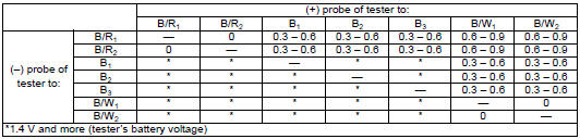
- Measure the voltage between the terminals using the multi-circuit testers as indicated in the following table. If the voltage is not within the specified value, replace the regulator/rectifier with a new one. Refer to “regulator / rectifier removal and installation” .
| Note if the tester reads 1.4 V and below when the tester probes are not connected, replace its battery. |
Special tool
 : 09900–25008 (multi circuit tester
set)
Tester knob indication
diode test (  )
)
Unit: v
- Connect the regulator/rectifier couplers and bind the clamp.
- Reinstall the removed parts.
 Regulator / rectifier removal and installation
Removal
Turn the ignition switch off.
Remove the right side cowling. Refer to “exterior parts removal and
installation” in section 9d .
Lift and support the fuel tank. Refer to ...
 Battery components
Anode plates
Separator (fiberglass plate)
Cathode plates
Upper cover breather
Stopper
Filter
Terminal
Safety valve
...
Other materials:
Front brake disc removal and installation
Removal
Remove the front wheel assembly. Refer to “front wheel assembly removal
and installation” in section 2d .
Remove the front brake disc.
Installation
Install the front brake disc in the reverse order of
removal. Pay attention to the following points:
make sure ...
Engine bottom side assembly
Assemble the engine bottom side in the reverse order of
disassembly. Pay attention to the following points:
Note
apply engine oil to each running and sliding
part before reassembling.
Breather oil return plate
When installing the breather oil return plate (1), apply
thread loc ...
Exhaust pipe bolt and muffler bolt inspection
Tighten exhaust pipe bolts and muffler bolts
initially at 1 000 km (600 miles, 2 months) and every
12 000 km (7 500 miles, 24 months) thereafter
Check the exhaust pipe bolts and muffler bolts to the
specified torque.
Tightening torque
exhaust pipe bolt (a): 23 n·m (2.3 Kgf-m, 16.5 Lbf-ft)
muf ...