Suzuki GSX-R 1000 Service Manual: Schematic and routing diagram
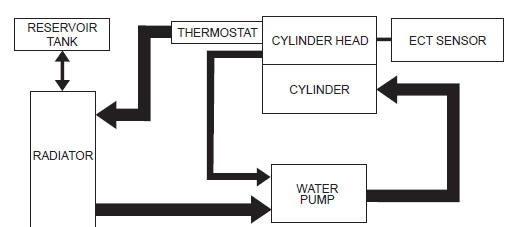
Cooling circuit diagram
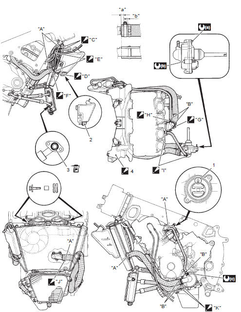
Water hose routing diagram
|
 Yellow
 White
White
 Clamp end
 Clamp end
 Cut off the
 Screw head
 Screw head
 Clamp end
 Clamp end
 Screw head
 Screw head
 6
6
 10 N·m
 13 N·m
 Apply engine oil.
 General description
Engine coolant description
Caution
use a high quality ethylene glycol base
anti-freeze, mixed with distilled water. Do
not mix an alcohol base anti-freeze and
different b ...
 Diagnostic information and procedures
Engine cooling symptom diagnosis
...
Other materials:
Show data when trouble (displaying data at
the time of DTC)
Use of sds
Ecm stores the engine and driving conditions (in the form of data as shown in
the figure) at the moment of the
detection of a malfunction in its memory. This data is called “show data when
trouble”.
Therefore, it is possible to know engine and driving conditions (e.G., Whether
...
Engine bottom side assembly
Assemble the engine bottom side in the reverse order of
disassembly. Pay attention to the following points:
Note
apply engine oil to each running and sliding
part before reassembling.
Breather oil return plate
When installing the breather oil return plate (1), apply
thread loc ...
Starter motor will not run
Note
make sure the fuses are not blown and the battery is fully-charged
before diagnosing.
Troubleshooting
Step
Action
Yes
No
1
Shift the transmission into neutral.
Grasp the clutch lever, turn on the ignition switch ...