Suzuki GSX-R 1000 Service Manual: Wiring harness routing diagram
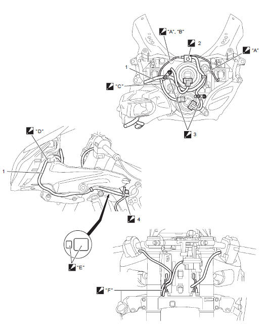
 Clamp Clamp
: pass the side-stand switch lead wire left side of the water bypass
hose and clamp them in this range. Cut off the excess tip
of the clamp. Clamp Clamp
: bind the lead wires at the blue taping point and face the clamp
end to the engine side.- Iat sensor
- Isc valve
 Clamp Clamp
: bind the lead wires with throttle body at blue taping point and
face the clamp end forward.- White coupler (for ignition coil #1)
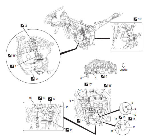
 Clamp: Clamp:
face the clamp end upward.- Stva lead wire
- Wiring harness
- Isc valve lead wire
- Regulator/rectifier lead wire
- Evap system purge control solenoid valve lead wire (e-33 only)
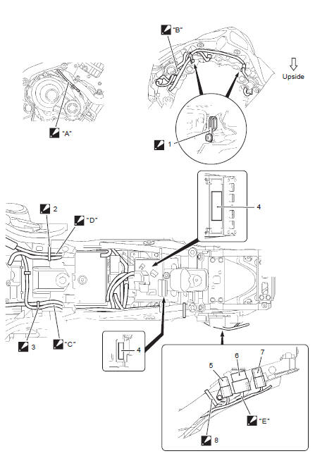
 Battery negative Battery negative
lead wire
: pass the battery negative lead wire in front of the pcv hose. (For
e-33, pass
the lead wire below the evap solenoid hoses, and between the evap
solenoid
lead wire and wiring harness.) Rear brake light Rear brake light
switch lead wire
: pass the rear brake light switch lead wire below the wiring
harness and battery
negative lead wire at the frame bridge part, then above the wiring
harness at
the fuel tank rail part. (For e-33, pass the brake light switch lead
wire between
evap solenoid bracket and frame.)- Crankcase breather (pcv) hose
- Starter motor lead wire
 Kp sensor lead wire Kp sensor lead wire
: route the ckp sensor lead wire in front of the pcv hose and above
the
battery negative lead wire. Pass Pass
the side-stand switch lead wire between the water hoses. Plate the Plate the
joint coupler to the engine side and pass the side-stand switch lead
wire and speed sensor lead wire left side of the water by-pass hose. Pass the Pass the
rear brake light switch lead wire between the frame and drain hose,
and under the clamp. Pass the Pass the
cmp sensor lead wire between ignition coil #1 and #2. Pass the Pass the
wiring harness above the air cleaner duct.- 60 ± 5°
|
Refer to “wire color symbols” in section 0a .
For e-02, 19, 24, 51
For e-03, 28
For e-14, 33
...
Service data
Electrical
Tightening torque specifications
Note
the specified tightening torque is described in the following.
“Wiring harness routing diagram”
Reference: ...
Other materials:
Pair control solenoid valve removal and
installation
Removal
Lift and support the fuel tank with the prop stay.
Refer to “fuel tank removal and installation” in section 1g .
Remove the air cleaner box. Refer to “air cleaner box removal and
installation” in section 1d .
Remove the pair control solenoid valve (1) along
with the pair ...
Tampering with noise control system prohibited
Federal law prohibits the following
acts or the causing there of;
The removal or rendering inoperative
by any person other
than for purposes of maintenance,
repair, or replacement,
of any device or element of
·design incorporated into any
new vehicle for the purpose of
noise ...
Right handlebar
Engine stop switch 1
"" Position
The ignition circuit is off. The
engine cannot start or run.
"" Position
The ignition circuit is on and the
engine can run.
Front brake lever 2
Apply the front brake by squeezing
the front brake lever towards
the grip. The brake ligh ...
 Tapping clamp
 Steel clamp
 Clamp:
 Take
Take
 Pass the
 Route the
 Pass the
 Place the
 Pass the
 Steel clamp
 Clamp
Clamp
 Clamp
Clamp
 Clamp
Clamp
 Be
Be
 Put the
 Do not
 Bring the
 Put the
 Pass
Pass
 10
10
 4 N·m (0.4
 1.5 N·m
 14 N·m
 145 N·m
 6.5 N·m
 11 N·m
 5.5 N·m
 Apply bond.
 Wiring diagram
 Specifications