Suzuki GSX-R 1000 Service Manual: Crankshaft journal bearing inspection and selection
Refer to “engine bottom side disassembly” (page 1d- 49).
Refer to “engine bottom side assembly” .
Inspection
- Inspect each upper and lower crankcase bearing for any damage.
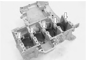
- Set the crankshaft onto the upper crank case.
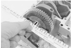
- Install the plastigauge onto each crankshaft journal.
Special tool
 (a): 09900–22301 (plastigage (0.025 –
0.076
Mm))
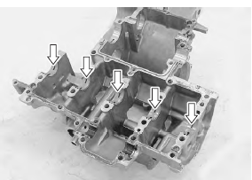
- Mate the lower crankcase with the upper crankcase.
- Tighten the crankshaft journal bolts (m9). Tighten each bolt a little at a time to equalize the pressure in the following two steps.
| Note do not rotate the crankshaft when a piece of plastigauge is installed. |
Tightening torque crankshaft journal bolt (m9): 18 n·m (1.8 Kgf-m, 13.0 Lbf-ft) then turn in 50°
- Remove the lower crankcase and measure the width of compressed plastigauge using the envelope scale. This measurement should be taken at the widest part of the compressed plastigauge. If the oil clearance exceeds the service limit, select the specified bearings from the bearing selection table.
Crankshaft journal oil clearance standard: 0.016 – 0.034 Mm (0.0006 – 0.0013 In)
Crankshaft journal oil clearance service limit: 0.080 Mm (0.0031 In)
Selection
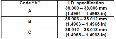
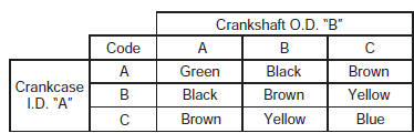
- Check the corresponding crankcase journal i.D.
Codes “a” ([a], [b] or [c]), which are stamped on the rear of the upper crankcase.
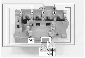
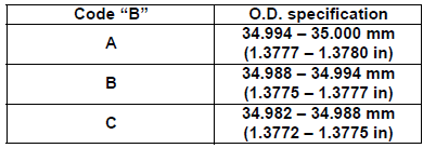
Crankcase journal i.D. Specification
- Check the corresponding crankshaft journal o.D.
Codes “b” ([a], [b] or [c]), which are stamped on the crankshaft.
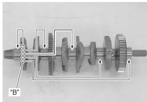
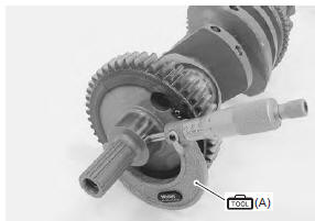
- Measure the crankshaft o.D. With the special tool. If any of the measurements are out of specification, replace the crankshaft.
Crankshaft journal o.D. Specification
Special tool
 (a): 09900–20202 (micrometer (25 –
50
mm))
- Select the specified bearings from the bearing selection table
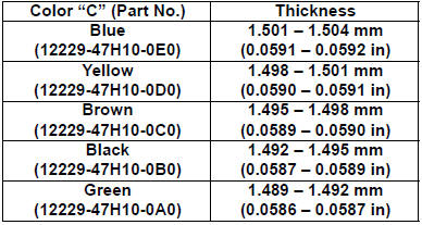
Bearing selection table
Bearing thickness specification
|
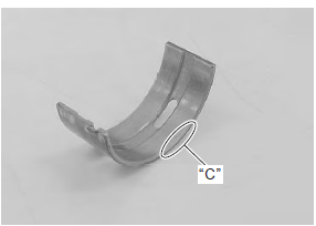
 Conrod crank pin bearing inspection and
selection
Conrod crank pin bearing inspection and
selection
Refer to “engine bottom side disassembly” (page 1d-
49).
Refer to “engine bottom side assembly” .
Inspection
Inspect the bearing surfaces for any signs of fusion,
pitting, burn or flaws. If ...
 Crankshaft thrust clearance inspection and
selection
Crankshaft thrust clearance inspection and
selection
Refer to “engine bottom side disassembly” (page 1d-
49).
Refer to “engine bottom side assembly” .
Inspection
With the crankshaft’s right-side and left-side thrust
bearings inserted into the ...
Other materials:
Ect sensor inspection
Refer to “dtc “c15” (p0115-h/l): ect sensor circuit malfunction” in section
1a .
Inspect the ect sensor in the following procedures:
remove the ect sensor. Refer to “ect sensor removal and installation” .
Connect the ect sensor (1) to the circuit tester and
place it in the o ...
Rear shock absorber removal and installation
Removal
Remove the right side cowling and side frame covers. Refer to “exterior
parts removal and installation” in section 9d .
Support the motorcycle with a jack to relieve load on
the rear shock absorber.
Remove the left muffler and muffler chamber heat guard no. 2. Refer ...
DTC “c14” (p0120-h/l): tp sensor circuit
malfunction
Detected condition and possible cause
Detected condition
Possible cause
C14
Output voltage is not within the following
range.
Difference between actual throttle opening
and opening calculated by ecm is larger
than specified value.
0.2 V ≤ Sensor ...