
Suzuki GSX-R 1000 Owners Manual: Damping force adjustment
The rebound and compression damping force can be individually adjusted by turning the respective adjusters. The rebound damping force adjuster 2 is located at the top of the front fork. The compression damping force adjuster 3 is located at the bottom of the front fork.
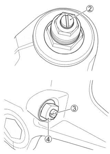
To adjust the damping force, set the adjuster to the standard setting first and then adjust the adjuster to the desired position.
To set the rebound and compression damping force, turn the adjuster clockwise until it stops and then turn it counterclockwise.
As you turn the adjuster, you will notice clicks. Count the number of clicks from fully turned-in position.
The standard rebound damping force setting is 9 clicks. The standard compression damping force setting is 14 clicks.
Turn the adjuster clockwise from the standard position to stiffen the damping force. Turn the adjuster counterclockwise to soften the damping force. The damping force should be adjusted gradually, 1/4 turn at a time, to fine-tune the suspension.
Note
: do not loosen the adjuster base 4, or front fork oil will ooze through the adjuster base.
 Warning Warning
Adjust the right and left front forks to the same settings. |
 Spring pre-load adjustment
To change the spring pre-load,
turn the adjuster 1 clockwise or
counterclockwise. Turning the
adjuster clockwise will increase
the spring pre-load. Turning the
adjuster counterclockwise will
...
 Rear suspension
...
Other materials:
Isc valve preset and opening initialization
When removing or replacing the isc valve, set the isc
valve to the following procedures:
turn the ignition switch on.
Set up the sds tool. (Refer to the sds operation
manual for further details.)
Click the “active control”.
Click the “isc learned value reset” (1) ...
Using the transmission
The transmission is provided to
keep the engine operating
smoothly in its normal operating
speed range. The gear ratios
have been carefully chosen to
meet the characteristics of the
engine. The rider should always
select the most suitable gear for
the prevailing conditions. Never
slip the c ...
Starter motor will not run
Note
make sure the fuses are not blown and the battery is fully-charged
before diagnosing.
Troubleshooting
Step
Action
Yes
No
1
Shift the transmission into neutral.
Grasp the clutch lever, turn on the ignition switch ...