
Suzuki GSX-R 1000 Service Manual: Fuel pump relay inspection
Refer to “electrical components location” in section 0a .
Inspect the fuel pump relay in the following procedures:
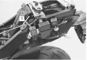
- remove the frame covers. Refer to “exterior parts removal and installation” in section 9d (page 9d- 6).
- Remove the fuel pump relay (1).
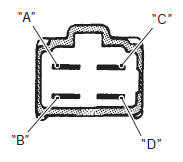
- First, check for insulation with the tester between terminals “a” and “b”. Next, check for continuity between “a” and “b” with 12 v voltage applied, positive (+) to terminal “c” and negative (–) to terminal “d”. If continuity does not exist, replace the relay with a new one.
Special tool
 : 09900–25008 (multi circuit tester
set)
Tester knob indication
continuity test (  )
)
Fuel hose inspection
Refer to “fuel line inspection” in section 0b (page 0b- 10).
Fuel level gauge inspection
Refer to “fuel level gauge inspection” in section 9c .
 Fuel discharge amount inspection
Keep away from fire or spark.
Spilled gasoline should be wiped off
immediately.
Work in a well-ventilated area.
Inspect the fuel discharge amo ...
 Fuel tank construction
Fuel tank heat
shield
: aluminum film side should face the engine side.
Fuel tank front cover
Fuel tank front bracket
Velcro fastenings
: clean the adhesiv ...
Other materials:
DTC “c41” (p0230-h/l): fp relay circuit
malfunction
Detected condition and possible cause
Detected condition
Possible cause
C41
No voltage is applied to fuel pump.
Fuel pump relay circuit open or short.
Fuel pump relay malfunction.
Fuel pump relay switch circuit is shorted to power
source.
...
Inspecting the drive chain
When inspecting the chain, look
for the following:
loose pins
damaged rollers
dry or rusted links
kinked or binding links
excessive wear
improper chain adjustment
If you find anything wrong with the
drive chain condition or adjustment,
correct the pr ...
DTC “c12” (p0335): ckp sensor circuit
malfunction.
Detected condition and possible cause
Detected condition
Possible cause
The signal does not reach ecm for 3 sec. Or more, after
receiving the starter signal.
Metal particles or foreign material being stuck on the
ckp sensor and rotor tip.
Ckp ...