Suzuki GSX-R 1000 Service Manual: Rear combination light removal and installation
Removal
- Remove the frame cover assembly. Refer to “exterior parts removal and installation” in section 9d .
- Remove the clamps (1).
- Disconnect the combination light coupler (2).
- Remove the rear combination light assembly (3).
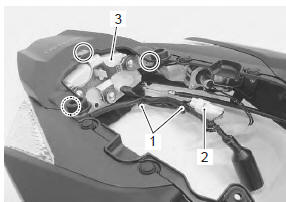
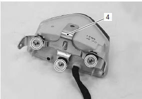
- Remove the combination light bracket (4).
Installation
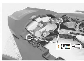
Install the rear combination light in the reverse order of removal. Pay attention to the following point:
- tighten the combination light mounting bolts (1) to the specified torque.
| Note when reusing the removed bolts (1), apply a small quantity of the thread lock to them. |
Tightening torque rear combination light mounting bolt (a): 2.8 N·m (0.28 Kgf-m, 2.0 Lbf-ft)
 : Thread lock cement
99000–32110
(thread lock cement super “1322” or
equivalent)
Rear combination light replacement
| Caution if led operation is abnormal, replace the rear combination light with a new one. |
 Rear lighting system construction
License plate light assembly
Reflex reflector (e-03, 28, 33 only)
Clamp
: clamp the license plate light lead wire
so as not to be slack.
Rear combination light
...
 License plate light components
License plate light bulb (12 v 5 w)
Lens cover
Lens
5
N·m (0.5 Kgf-m, 3.5 Lbf-ft)
...
Other materials:
Exhaust control system construction
Excv cable no. 1 (Cl)
Excv cable no. 2 (Op)
When
loosening or tightening the pulley bolt, be sure to fix the
pulley with an adjustable wrench, or excva may get damaged.
5 N·m (0.5 Kgf-m, 3.5 Lbf-ft)
42 – 43 Mm (1.65 – 1.69 In)
60 – 61 Mm (2.36 – ...
Rear wheel components
Rear axel nut
Collar
Dust seal
Bearing
Retainer
Rear sprocket
Sprocket mounting drum
Wheel damper
Bearing
Spacer
Air valve
Rear wheel
Wheel balancer
Rear tire
Dust seal
Collar
Rear brake disc
Rear axle
1 ...
Battery
Battery connection in reverse polarity is strictly
prohibited. Such a wrong connection will damage the
components of the fi system instantly when reverse
power is applied.
Removing any battery terminal of a running engine is
strictly prohibited. The moment such removal is made,
...