Suzuki GSX-R 1000 Service Manual: Excv cable removal and installation
Removal
- Turn the ignition switch off.
- Remove the front seat. Refer to “exterior parts removal and installation” in section 9d (page 9d- 6).
- Remove the left side cowling. Refer to “exterior parts removal and installation” in section 9d .
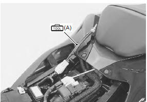
- Connect the special tool (mode select switch) to the dealer mode coupler. Refer to “self-diagnostic procedures” in section 1a .
- After turning the mode select switch on, turn the ignition switch on.
Special tool
 (a): 09930–82720 (mode selection
switch)
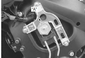
- Check that the cable slots of the excva pulley comes to the middle (adjustment position) “a”.
- Turn the ignition switch off.
| Caution before removing the excv cables, be sure to set the excva pulley to the adjustment position. |
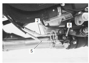
- Loosen the lock-nut (1) on the no. 2 Cable (2) and turn in the cable adjuster (3) fully.
- Loosen the lock-nut (4) on the no. 1 Cable (5) and turn in the cable adjuster (6) fully.
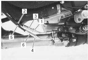
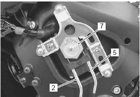
- Disconnect the no. 2 Cable (2) and no. 1 Cable (5) from the excva pulley (7).
- Loosen the lock-nuts.
- Disconnect the no. 2 Cable (2) and no. 1 Cable (5) from the excv pulley (8).
Installation
| Caution the cable slots of excva pulley must be located adjustment position. |
- Temporarily connect the excv cable no. 1 (47H0cl) (1) and no. 2 (47H0op) (2) to the exhaust pipe and excv pulley.
| Note the excv cables are identified by the letters. No. 1 Cable (1): 47h0cl no. 2 Cable (2): 47h0op |
- Tighten the lock-nuts (3) on the no. 1 Cable.
- Adjust the inner cable length “a” of no. 1 Cable in 42 – 43 mm (1.65 – 1.69 In) by turning the adjuster (4), then tighten the lock-nuts (5).
- Turn in the adjuster (6) on the no. 2 Cable fully.
- Turn the no. 2 Cable adjuster (7) in or out until the
inner cable length “b” becomes 60 – 61 mm (2.36 –
2.40 In).
After adjusting the inner cable length “b”, tighten the lock-nuts (8).

- Connect the other end of excv cable no. 1 (1) And no. 2 (2) To the excva pulley (9).
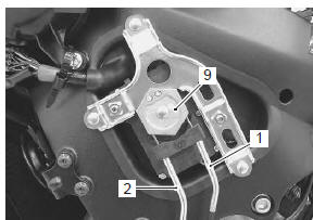
- After connecting the no. 2 Cable (2), loosen the locknut (10) and turn the adjuster (6) in or out until 11 – 12 mm (0.43 – 0.47 In) of the thread length “c” on the cable adjuster can be provided and tighten the locknut (10).
- Inspect the excva position sensor output voltage.
Refer to “excva adjustment” .
 Exhaust system components
Exhaust pipe gasket
Exhaust pipe assembly
Ho2 sensor
Connector
: install the connector so that the
chamfer side faces backward.
Muffler chamber
Muffler ...
 Excva removal and installation
Removal
Turn the ignition switch off.
Remove the left side cowling. Refer to “exterior parts removal and
installation” in section 9d .
Connect the special tool (mode select swit ...
Other materials:
Conclusion
Traffic, road and weather conditions
vary. Other motorists'
actions are unpredictable. Your
motorcycle's condition can
change. These factors can best
be dealt with by giving every ride
your full attention.
Circumstances beyond your control
could lead to an accident. You
need to prepare fo ...
Crankcase emission control system
description
The engine is equipped with a pcv system to prevent discharging crankcase
emissions into the atmosphere. Blow-by
gas in the engine is constantly drawn into the crankcase, which is returned to
the combustion chamber through the
pcv (breather) hose, air cleaner and throttle body.
...
Pair system inspection
Inspect pair system
every 12 000 km (7 500 miles, 24 months)
Inspect the pair (air supply) system periodically. Refer to “pair system
inspection” in section 1b .
Throttle valve synchronization
Inspect throttle valve synchronization
initially at 1 000 km (600 miles, 2 months) (e-33 only)
and ...