Suzuki GSX-R 1000 Service Manual: Tightening torque specifications
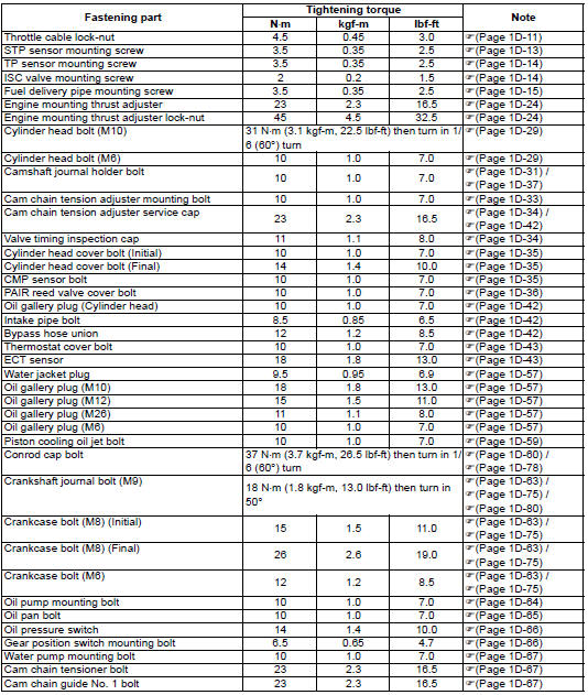
| Note the specified tightening torque is described in the following. “Throttle cable routing diagram” “throttle body components” “throttle body construction” “engine assembly installation” |
Reference
: for the tightening torque of fastener not specified in this section, refer to “tightening torque list” in section 0c .
 Service data
Valve + guide
unit: mm (in
Camshaft + cylinder head
unit: mm (in
Cylinder + piston + piston ring
unit: mm (in)
Conrod + crankshaft
unit: mm (in)
Balancer
unit: mm (in)
Th ...
 Special tools and equipment
Recommended service material
Note
required service material is also described in the following.
“Throttle body components” “engine bottom side assembly”
Special tool
...
Other materials:
Throttle cable play inspection and adjustment
Inspect throttle cable play
initially at 1 000 km (600 miles, 2 months) and every
6 000 km (4 000 miles, 12 months) thereafter
Inspect and adjust the throttle cable play “a” as follows:
Throttle cable play “a”
2.0 – 4.0 Mm (0.08 – 0.16 In)
Remove the boot (1).
Loosen the lock-nu ...
Starting the engine
Before attempting to start the
engine, make sure:
The transmission is in neutral.
The engine stop switch is in
the "" position.
Note: this motorcycle has a
starter interlock system for the
ignition and starter circuit. The
engine can only be started if:
...
Show data when trouble (displaying data at
the time of DTC)
Use of sds
Ecm stores the engine and driving conditions (in the form of data as shown in
the figure) at the moment of the
detection of a malfunction in its memory. This data is called “show data when
trouble”.
Therefore, it is possible to know engine and driving conditions (e.G., Whether
...